Understanding your 2004 Ford F-150’s fuse box is crucial for diagnosing and resolving electrical issues, especially when it comes to your OBD2 port. This guide will walk you through the fuse box locations and diagrams for your 2004 Ford F-150, with a specific focus on fuses related to the OBD2 system, also known as the diagnostic connector. Locating the correct fuse is the first step in troubleshooting problems with your vehicle’s onboard diagnostics.
Your 2004 Ford F-150 is equipped with three distinct fuse boxes, each serving different circuits within your truck. Knowing where these fuse boxes are and what fuses they control can save you time and effort in electrical repairs. Let’s explore each location and its corresponding fuse diagram to help you pinpoint the “04 Ford F150 Obd2 Fuse” or any other fuse you might need.
Fuse Box Locations on a 2004 Ford F-150
To effectively troubleshoot electrical problems, you need to know where to find each fuse box. Your 2004 F-150 contains the following fuse box locations:
- Passenger Compartment Fuse Panel: This fuse box is located inside the cabin of your F-150. It is often found on the passenger side, beneath the dashboard area. This panel houses fuses and relays that control many of the interior electrical functions of your vehicle.
- Auxiliary Relay Box (with DRL): This box is located in the engine compartment. The presence of “DRL” in the name indicates it’s for models equipped with Daytime Running Lights.
- Auxiliary Relay Box (without DRL): Also located in the engine compartment, this version is for 2004 Ford F-150 models that are not equipped with Daytime Running Lights.
Let’s delve into the diagrams for each of these fuse boxes to identify the “04 ford f150 obd2 fuse” and other important circuits.
Passenger Compartment Fuse Panel Diagram
The passenger compartment fuse panel, sometimes referred to as the power distribution box, is a primary location for many essential fuses in your 2004 Ford F-150. Here is a diagram and table detailing the fuses within this box.
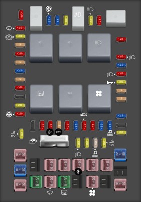
 2004 Ford F-150 Passenger Compartment Fuse Box Diagram
Alt text: Diagram showing the layout of the passenger compartment fuse box in a 2004 Ford F-150, highlighting fuse locations and their corresponding numbers.
| Type | No. | Description |
|---|---|---|
| Fuse MINI 10A | 1 | Run/Accessory – Wipers, Instrument cluster |
| Fuse MINI 20A | 2 | Stop/Turn lamps, Speed control deactivate switch |
| Fuse MINI 5A | 3 | Power mirrors, Memory logic power, Memory seats and pedals |
| Fuse MINI 10A | 4 | DVD battery power |
| Fuse MINI 5A | 5 | Keep alive memory for Powertrain Control Module (PCM) and climate control module |
| Fuse MINI 15A | 6 | Parklamps, BSM, Instrument panel illumination |
| Fuse MINI 5A | 7 | Radio (start signal) |
| Fuse MINI 10A | 8 | Heated mirrors, Switch indicator |
| Fuse MINI 20A | 10 | Trailer tow back-up lamps relay (PCB1), Trailer tow parklamp relay (R201) |
| Fuse MINI 10A | 11 | A/C clutch, 4×4 solenoid |
| Fuse MINI 10A | 13 | Climate control module power |
| Fuse MINI 10A | 14 | Back-up lamp and Daytime Running Lamps (DRL) relay coil, A/C pressure switch, Brake-shift interlock solenoid |
| Fuse MINI 5A | 15 | Overdrive cancel, Cluster, Brake-Shift Interlock (BSI) |
| Fuse MINI 10A | 16 | ABS module (Run/Start power) |
| Fuse MINI 15A | 17 | Fog lamp relay (R202) |
| Fuse MINI 10A | 18 | Run/Start feed – Flasher relay, Electrochromatic mirror, Heated seats, BSM, Compass, RSS (Reverse Sensing System) |
| Fuse MINI 10A | 19 | Restraints (Air bag module) |
| Fuse MINI 15A | 20 | PCM 4×4 power |
| Fuse MINI 15A | 21 | Cluster keep alive power |
| Fuse MINI 10A | 22 | Delayed accessory power for audio, power door lock switch and moonroof switch illumination |
| Fuse MINI 10A | 23 | RH low beam headlamp |
| Fuse MINI 15A | 24 | Battery saver power for demand lamps |
| Fuse MINI 10A | 25 | LH low beam headlamp |
| Fuse MINI 20A | 26 | Horn relay (PCB3), Horn power |
| Fuse MINI 5A | 27 | Passenger Air bag Deactivation (PAD) warning lamp, Cluster air bag warning lamp, Cluster RUN /START power |
| Fuse MINI 5A | 28 | SecuriLock transceiver (PATS) |
| Fuse MINI 15A | 29 | PCM 4×4 power |
| Fuse MINI 20A | 31 | Radio power |
| Fuse MINI 15A | 32 | Vapor Management Valve (VMV), A/C clutch relay, Canister vent, Heated Exhaust Gas Oxygen (HEGO) sensors #11 and #21, CMCV, Mass Air Flow (MAF) sensor, VCT |
| Fuse MINI 15A | 33 | Shift solenoid, CMS #12 and #22 |
| Fuse MINI 20A | 34 | Fuel injectors and PCM power |
| Fuse MINI 20A | 35 | Instrument cluster high beam indicator, High beam headlamps |
| Fuse MINI 10A | 36 | Trailer tow right turn/stop lamps |
| Fuse MINI 20A | 37 | Rear power point |
| Fuse MINI 25A | 38 | Subwoofer power |
| Fuse MINI 20A | 39 | Instrument panel power point |
| Fuse MINI 20A | 40 | Low beam headlamps, DRL |
| Fuse MINI 20A | 41 | Cigar lighter, Diagnostic connector power |
| Fuse MINI 10A | 42 | Trailer tow left turn/stop lamps |
| Fuse FMX/JCase 30A | 101 | Starter solenoid |
| Fuse FMX/JCase 20A | 102 | Ignition switch feed |
| Fuse FMX/JCase 20A | 103 | ABS valves |
| Fuse FMX/JCase 30A | 105 | Electric trailer brakes |
| Fuse FMX/JCase 30A | 106 | Trailer tow battery charge |
| Fuse FMX/JCase 30A | 107 | Power door locks (BSM) |
| Fuse FMX/JCase 30A | 108 | Passenger power seat |
| Fuse FMX/JCase 30A | 109 | Driver power seat, Adjustable pedals |
| Fuse FMX/JCase 30A | 111 | 4×4 relays |
| Fuse FMX/JCase 40A | 112 | ABS pump power |
| Fuse FMX/JCase 30A | 113 | Wipers and washer pump |
| Fuse FMX/JCase 40A | 114 | Heated backlite, Heated mirror power |
| Fuse FMX/JCase 30A | 116 | Blower motor |
| Fuse FMX/JCase 30A | 118 | Heated seats |
| Circuit breaker MAXI | 401 | Power windows, Moonroof, Power sliding backlite |
| Relay | R01 | Starter solenoid |
| Relay | R02 | Accessory delay |
| Relay | R03 | Hi-beam headlamps |
| Relay | R04 | Heated backlite |
| Relay | R05 | Trailer tow battery charge |
| Relay | R06 | Blower motor |
| Relay | R201 | Trailer tow park lamps |
| Relay | R202 | Fog lamps |
| Relay | R203 | PCM |
OBD2 Fuse Location: Looking at the table, fuse number 41 in the Passenger Compartment Fuse Panel is explicitly labeled “Diagnostic connector power“. This 20A fuse is the “04 ford f150 obd2 fuse” you are looking for. If you are experiencing issues with your OBD2 scanner not powering on or connecting to your vehicle’s computer, this is the first fuse to check.
Auxiliary Relay Box (with DRL) Diagram
This auxiliary relay box, found in the engine compartment of 2004 Ford F-150 models with Daytime Running Lights (DRL), contains additional relays and fuses.
 2004 Ford F-150 Auxiliary Relay Box Diagram with DRL
Alt text: Fuse diagram for the auxiliary relay box with DRL in a 2004 Ford F-150, showing relay and fuse positions and descriptions.
| Type | No. | Description |
|---|---|---|
| Fuse ATO 5A | F01 | Clockspring illumination |
| Relay | R01 | 4×4 CCW |
| Relay | R02 | 4×4 CW |
| Relay | R03 | Daytime Running Lamps (DRL) [if equipped, otherwise not used] |
| Relay | R201 | DRL |
| Relay | R202 | A/C clutch |
| Diode ATO | D01 | A/C clutch diode |
This fuse box diagram does not list a fuse directly related to the OBD2 port. However, it controls other vehicle systems that might indirectly impact diagnostics.
Auxiliary Relay Box (without DRL) Diagram
For 2004 Ford F-150 models without Daytime Running Lights (DRL), the auxiliary relay box in the engine compartment may have a slightly different configuration.
 2004 Ford F-150 Auxiliary Relay Box Diagram without DRL
Alt text: Diagram of the auxiliary relay box without DRL for a 2004 Ford F-150, detailing the layout and function of relays and fuses within this engine compartment box.
| Type | No. | Description |
|---|---|---|
| Fuse ATO 5A | F01 | Clockspring illumination |
| Relay | R01 | 4×4 CCW |
| Relay | R02 | 4×4 CW |
| Relay | R201 | DRL |
| Relay | R202 | A/C clutch |
| Diode ATO | D01 | A/C clutch diode |
Similar to the DRL version, this auxiliary fuse box diagram does not show a direct OBD2 fuse.
Troubleshooting OBD2 Port Issues on Your 2004 Ford F-150
If your OBD2 scanner is not working on your 2004 Ford F-150, follow these troubleshooting steps:
-
Check Fuse #41 (20A) in the Passenger Compartment Fuse Panel: This is the primary fuse for the diagnostic connector power. Inspect the fuse to see if it is blown. Replace it with a new 20A fuse if necessary.
-
Inspect the OBD2 Port: Visually check the OBD2 port for any damage or debris that might be preventing a good connection with your scanner.
-
Test with a Different Scanner: If possible, try using a different OBD2 scanner to rule out an issue with your scanner itself.
-
Check Wiring: If the fuse is good and the port looks clean, there might be a wiring issue. Consult a wiring diagram for your 2004 F-150 or seek professional help to diagnose wiring problems.
-
PCM Issues: In rare cases, a problem with the Powertrain Control Module (PCM) could affect the OBD2 port. However, rule out simpler issues like fuses and wiring first.
By using these fuse box diagrams and understanding the location of the “04 ford f150 obd2 fuse”, you can take a proactive approach to diagnosing and resolving electrical and diagnostic issues in your 2004 Ford F-150. Remember to always consult your owner’s manual for the most accurate information specific to your vehicle.