Maintaining your 2005 Ford E-350 in top condition requires understanding its electrical system, and a crucial part of that is knowing your fuse box locations and layouts. Fuses protect your vehicle’s electrical circuits from overloads, preventing damage to components. This guide will walk you through the fuse box diagrams for your 2005 Ford E-350, ensuring you can quickly identify and replace any blown fuses. While fuses are not directly related to the OBD2 port’s functionality, understanding your vehicle’s electrical system is essential for diagnosing issues that might arise when using your OBD2 scanner.
Understanding the Fuse Box Locations on Your 2005 Ford E-350
Your 2005 Ford E-350 is equipped with multiple fuse boxes, each serving different circuits within the vehicle. Knowing the location of each fuse box is the first step in troubleshooting electrical problems. This model features four distinct fuse box locations: the passenger compartment fuse panel, the power distribution box, and two relay modules. Let’s explore each of these in detail.
Passenger Compartment Fuse Panel Diagram
The passenger compartment fuse panel is typically the first place to check for many common electrical issues inside your Ford E-350. This fuse box is usually located beneath the dashboard on the passenger side. Consult the diagram below to identify the fuses within this panel.
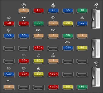 2005 Ford E-350 passenger compartment fuse panel diagram
Here’s a breakdown of the fuses in the passenger compartment fuse panel:
| Fuse Number | Ampere | Circuit Protected |
|---|---|---|
| 1 | 5A | 4-Wheel Anti-lock Brake System (4WABS) module |
| 2 | 10A | Remote Keyless Entry (RKE), O/D cancel |
| 3 | 15A | Trip computer, Radio, Video Cassette Player (VCP) and video screens, Overhead console |
| 4 | 15A | Courtesy lamps |
| 5 | 30A | Power lock switches, Power locks without RKE |
| 6 | 10A | Brake-shift interlock, Daytime Running Lamps (DRL) module |
| 7 | 10A | Multi-function switch, Turn signals |
| 8 | 30A | Radio capacitor(s) Ignition coil, Powertrain Control Module (PCM) diode, PCM power relay |
| 9 | 5A | Wiper control module |
| 10 | 20A | Main light switch, Park lamps, License lamp (external lamps), Multi-function switch (flash-to-pass) |
| 11 | 15A | Multi-function switch (hazards), Brake lamp switch, Brake lamps |
| 12 | 15A | Back-up lamps, Auxiliary battery relay [gasoline engine only], Trailer tow relay |
| 13 | 15A | Blend door actuator, Function selector switch |
| 14 | 5A | Instrument cluster |
| 15 | 5A | Trailer battery charge relay, Cluster |
| 16 | 30A | Power seats |
| 17 | 5A | Power mirrors |
| 20 | 10A | Restraints |
| 22 | 15A | Memory power radio, Rear seat video control unit, Battery saver relay, Instrument cluster, Courtesy lamp relay, Accessory delay relay |
| 23 | 20A | Power locks w/RKE |
| 25 | 10A | Left headlamp (low beam) |
| 26 | 20A | Cigar lighter, Diagnostics |
| 27 | 5A | Radio |
| 30 | 15A | Headlamps (high beam indicator) |
| 31 | 10A | Right headlamp (low beam) |
| 32 | 20A | Power point #1 (instrument panel) |
| 33 | 10A | Start relay |
| 36 | 5A | Instrument illumination |
| 39 | 10A | Trailer tow electric brake, Center High-Mounted Stop Lamp (CHMSL), Brake lamps |
| 40 | 20A | Power point #2 (2nd row seating position – driver side) |
| 41 | 30A | Modified vehicle |
| 42 | CB 42 | Power windows |
| 44 | CB 44 | Wiper/washer |
Power Distribution Box Diagram
The power distribution box, often located in the engine compartment, houses fuses and relays for high-power circuits. This box is critical for systems like the engine, braking, and lighting.
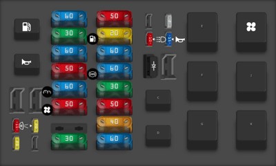 2005 Ford E-350 power distribution box diagram in the engine compartment
Here’s the layout and function of the fuses and relays in the power distribution box:
| Fuse/Relay | Number | Type | Description |
|---|---|---|---|
| 1 | 1 | Diode ATO | Powertrain Control Module (PCM) diode |
| 3 | 3 | Fuse MINI 10A | Daytime Running Lamps (DRL) module, A/C clutch |
| 5 | 5 | Fuse MINI 15A | Horn relay |
| 6 | 6 | Fuse MINI 2A | Brake pressure switch |
| 7 | 7 | Fuse MAXI 60A | Ignition switch, Fuse panel, Accessory delay |
| 8 | 8 | Fuse MAXI 40A | Trailer battery charge relay |
| 9 | 9 | Fuse MAXI 50A | Modified vehicle power |
| 10 | 10 | Fuse MAXI 30A | Electric brake controller |
| 11 | 11 | Fuse MAXI 60A | 4-Wheel Anti-lock Brake System (4WABS) |
| 12 | 12 | Fuse MAXI 60A | I/P fuses 29, 34, 35, 40 and 41 |
| 13 | 13 | Fuse MAXI 20A | Fuel pump relay |
| 14 | 14 | Fuse MAXI 50A | Auxiliary blower relay |
| 15 | 15 | Fuse MAXI 30A | Main light switch |
| 17 | 17 | Fuse MAXI 50A | Blower motor relay (blower motor) |
| 18 | 18 | Fuse MAXI 60A | Engine compartment fuses 3, 5, 23 and 26, Instrument panel fuses 26 and 32, Start relay |
| 19 | 19 | Fuse MAXI 50A | IDM relay [Diesel engine only] |
| 20 | 20 | Fuse MAXI 60A | Auxiliary battery relay [gasoline engine only], PDB fuses 8 and 24 |
| 21 | 21 | Fuse MAXI 30A | PCM power relay, PDB fuse 27 |
| 22 | 22 | Fuse MAXI 60A | I/P fuses 4, 5, 10, 11, 16, 17, 22 and 23, Circuit breaker 44 |
| 24 | 24 | Fuse MINI 20A | Trailer tow running lamps and back-up lamp relays |
| 26 | 26 | Fuse MINI 20A | Trailer tow turn signals |
| 27 | 27 | Fuse MINI 10A | PCM |
| A | A | Relay | Fuel pump relay |
| B | B | Relay | Horn relay |
| C | C | Relay | Trailer back-up lamps relay |
| D | D | Relay | Trailer running lamps relay |
| E | E | Relay | Trailer battery charge relay |
| F | F | Relay | IDM relay [Diesel only] |
| G | G | Relay | PCM relay |
| H | H | Relay | Blower motor relay |
| J | J | Relay | Accessory delay relay |
| K | K | Relay | Start relay |
Relay Modules: Instrument Panel and Engine Compartment
In addition to the main fuse boxes, your 2005 Ford E-350 includes relay modules. These modules, located in both the instrument panel and engine compartment, control various electrical functions.
Instrument Panel Relay Module Diagram
 2005 Ford E-350 instrument panel relay module diagram
| Relay Number | Description |
|---|---|
| 1 | Interior lamps |
| 2 | Open |
| 3 | Open |
| 4 | Battery saver |
Engine Compartment Relay Module Diagram
 2005 Ford E-350 engine compartment relay module diagram
| Relay Number | Description |
|---|---|
| 1 | PCM back-up lamp |
| 2 | A/C control |
| 3 | Trailer tow right turn |
| 4 | Trailer tow left turn |
OBD2 Port and Diagnostic Relevance
While there isn’t a specific fuse labeled “OBD2,” the diagnostic system in your 2005 Ford E-350 relies on several circuits that are fuse-protected. The OBD2 port itself is typically powered by circuits related to the Powertrain Control Module (PCM) and the instrument panel. If you’re experiencing issues with your OBD2 scanner not powering on or connecting, checking fuses related to the PCM (like fuse #27 – 10A in the Power Distribution Box) and the diagnostic fuse (fuse #26 – 20A in the Passenger Compartment Fuse Panel) is a good starting point.
The OBD2 port is usually located under the dashboard on the driver’s side. It provides access to your vehicle’s computer system for diagnostics and troubleshooting. Understanding the fuse system in conjunction with your OBD2 port can significantly aid in diagnosing electrical and engine-related problems in your 2005 Ford E-350.
Conclusion
Knowing the fuse box diagrams for your 2005 Ford E-350 is a valuable skill for any vehicle owner. By using these diagrams, you can efficiently troubleshoot and resolve minor electrical issues, saving time and potentially avoiding costly repairs. Remember to always replace a blown fuse with one of the same amperage to prevent further electrical problems. For complex issues or if you are unsure, always consult a qualified mechanic.