Modifying your stock truck wiring harness for a cleaner, more efficient setup is a common task for those undertaking engine swaps or simplifying their engine bay. For enthusiasts working with 1999-2007 GM Vortec truck engines, understanding the intricacies of the fuse block and OBD2 port wiring is crucial. This guide will delve into the “12 Pin Obd2 Port Fuse Block Lt1 Wiring Diagram” concept, even though the term might be slightly misleading, and clarify how to approach wiring modifications effectively for your Vortec engine harness.
While the specific phrase “12 pin obd2 port fuse block lt1 wiring diagram” might not directly correspond to a single, standard component, it highlights key areas in engine wiring: the OBD2 port for diagnostics, the fuse block for power distribution and circuit protection, and the wiring principles often associated with GM LT1 and later engine families, including Vortec/LS series.
This article serves as your expert guide to navigate these wiring aspects, ensuring your modified harness is reliable, safe, and optimized for performance. We’ll break down the essential components, wiring strategies, and best practices for modifying your Vortec truck harness, focusing on the fuse block and OBD2 port integration.
Understanding the Stock Vortec Truck Wiring Harness
The factory wiring harness in 1999-2007 GM trucks is designed for comprehensive vehicle functionality. It includes numerous circuits that may not be necessary when performing an engine swap or creating a standalone harness. The under-hood fuse block is a central distribution point, and the OBD2 port is vital for engine diagnostics and tuning.
The C2 Fuse Block Connector:
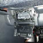
A key element in the stock harness is the C2 connector, which plugs into the bottom of the under-hood fuse block. This junction block is part of the main engine harness and carries power to various engine components. Many wires converge at this block, including individual power feeds for each injector.
Alt Text: Detailed view of the C2 Underhood Fuse Block Connector, highlighting its role as a central junction point in the Vortec engine harness.
Simplifying the Fuse Block Wiring:
One common modification is to streamline the fuse block wiring. In the stock configuration, each injector might have its own power wire running to the fuse block. For simplification, these can be combined and powered through a single fuse. This internal consolidation is effectively what happens within the fuse block itself, but understanding this allows for external wiring simplification when modifying the harness.
Basic Wiring for Engine Operation:
If your primary goal is simply to get the engine running, the process can be surprisingly basic. By identifying and connecting just a few key wires, you can achieve engine startup:
- Pink Wires (Ignition Power): All pink wires at the C2 fuse block plug can be connected to a 12V+ key-switched power source (hot in “ON” and “CRANK”).
- Orange Wires (Battery Power): The two orange wires should be connected to a constant 12V+ battery source.
- Fuel Pressure: Ensure adequate fuel pressure is supplied to the fuel rails.
- Starter Circuit: Connect the starter circuit to crank the engine.
With these basic connections, the engine should run, as the PCM (Powertrain Control Module) will be powered and functional. However, this rudimentary setup bypasses essential safety and diagnostic features.
The Importance of Proper Circuit Protection:
Directly combining all pink wires into a single power source without individual circuit protection is strongly discouraged. This approach creates a significant risk of electrical issues. If a short circuit occurs in any of the combined circuits, it can lead to:
- Melted Wires: Overcurrent can overheat and melt wire insulation.
- Electrical Fires: In extreme cases, shorts can ignite flammable materials.
Properly fusing each circuit is crucial for safety and reliability. The fuse block is designed for this purpose, and any harness modification should maintain or improve upon this safety standard.
Integrating the OBD2 Port for Diagnostics
The OBD2 (On-Board Diagnostics II) port is essential for modern engine management. It allows you to:
- Read Diagnostic Trouble Codes (DTCs): Identify engine and transmission problems.
- Monitor Engine Parameters: Observe live data such as sensor readings, RPM, temperature, and more.
- Flash/Tune the PCM: Reprogram the PCM for performance tuning or parameter adjustments.
OBD2 Port Wiring:
For a standalone harness, proper wiring of the OBD2 port is necessary. The key connection from the PCM to the OBD2 port is typically the Serial Data wire.
- Blue Connector C1, Pin 58 (Dk Green – Serial Data): This wire is the Class 2 Serial Data line and connects to pin 2 of the OBD2 port.
Alt Text: Components needed for building a custom fuse block and integrating the OBD2 port, essential for standalone harness setups.
12-Pin OBD2 Port Configuration:
While the term “12 pin OBD2 port” is used in the keyword, standard OBD2 ports are typically 16-pin. It’s possible “12 pin” refers to a specific subset of critical pins often utilized in simplified or standalone applications, or it might be a slight misnomer in common terminology. Regardless, understanding the function of each pin in the 16-pin OBD2 port is vital. For basic diagnostic functionality in a standalone harness, you’ll primarily need to focus on:
- Pin 2: J1850 Line (VPW or PWM) or CAN Bus (depending on the vehicle year/protocol): Serial data communication.
- Pin 4 & 5: Ground: Chassis and signal grounds.
- Pin 16: Battery Power (12V+): Power supply for the diagnostic tool.
Refer to specific OBD2 port pinout diagrams for your vehicle year and PCM to ensure accurate wiring.
Essential PCM Connections for Standalone Harnesses
Beyond the fuse block and OBD2 port, several PCM connections are crucial for a functional standalone harness. These connections control essential engine and transmission functions. Here’s a breakdown of key wires from the PCM connectors (Blue C1 and Red/Green C2) for 1999-2007 Vortec engines:
Blue Connector C1:
- Pin 33 – Purple – TCC Brake Switch: For torque converter clutch (TCC) operation in automatic transmissions. Requires 12V+ and is interrupted by the brake switch.
- Pin 42 – Empty – Fan 1 Control: Output for controlling an electric cooling fan relay (PCM provides a ground signal to activate the relay).
- Pin 58 – Dk Green – Serial Data: OBD2 diagnostic data line (pin 2 of OBD2 port).
- Pin 19 & 75 – Pink – 12V+ KEY Power: Ignition power source for the PCM (hot in “ON” and “CRANK”).
- Pin 20 & 57 – Orange – 12V+ BATTERY Power: Constant battery power source for PCM memory and keep-alive functions.
Red/Green Connector C2:
- Pin 9 – Dk Green/White – Fuel Pump Relay Control: PCM output to control the fuel pump relay (PCM provides 12V+ to activate the relay).
- Pin 10 – White – Engine Speed Signal (Tach): Tachometer signal output. PCM default is 4-cylinder signal, programmable to 8-cylinder.
- Pin 33 – Dk Green – Fan 2 Control: Second electric fan control output (programmable, may have been used for HVAC recirculation in some applications).
- Pin 46 – MIL Control (Check Engine Light): Malfunction Indicator Lamp (MIL) or “Check Engine Light” control (PCM provides a ground to turn on the light).
- Pin 50 – Dk Green/White – VSS (Vehicle Speed Sensor): Vehicle Speed Sensor signal output (4000 pulses per mile), useful for cruise control or speedometers.
.jpg)
Alt Text: Labeled wires from the PCM connectors, indicating essential circuits like fuel pump relay, brake switch signal, and service engine light for standalone harness creation.
Streamlining Your Harness Modification:
The process of modifying a Vortec truck harness involves several key steps to achieve a clean and reliable standalone setup:
- Disconnect and Disassemble: Begin by disconnecting the harness and carefully removing wire coverings and tape to access individual wires.
- Identify and Label Wires: Use wiring diagrams (like the linked pinouts for 1999-2007 models) to identify and label essential wires. Focus on power, grounds, PCM connections, and OBD2 port wiring.
- Remove Unnecessary Wires: Systematically remove wires that are not needed for your standalone application. This includes circuits for emissions controls, body control functions, and accessories you may not be using. Cut wires close to splice packs and connectors you are eliminating.
- Simplify Power Distribution: Re-route and combine power wires as needed, ensuring each critical circuit is properly fused. Utilize relays for high-current devices like fuel pumps and fans, controlled by the PCM outputs.
- Integrate Fuse Block and OBD2 Port: Incorporate a fuse block for circuit protection and an OBD2 port for diagnostics into your modified harness.
- Re-wrap and Protect: Once modifications are complete, carefully re-wrap the harness with automotive tape, ensuring wires are protected from abrasion and the elements.
.jpg)
Alt Text: A Vortec harness completely stripped and with unnecessary wires removed, ready for simplification and integration of essential components like the fuse block and OBD2 port.
Best Practices for Vortec Harness Modification
- Use Wiring Diagrams: Always refer to accurate wiring diagrams for your specific year and model of Vortec truck harness. The links provided in the original article are valuable resources.
- Label Everything: Thoroughly label all wires as you modify the harness. This will save time and prevent errors during reassembly and troubleshooting.
- Maintain Circuit Protection: Never bypass fuses or circuit breakers. Proper fusing is crucial for safety and preventing electrical damage.
- Use Quality Components: Utilize automotive-grade wire, connectors, fuses, relays, and terminals for durability and reliability.
- Test Thoroughly: After completing your harness modification, meticulously test all circuits and connections before installing and starting the engine.
Conclusion
Modifying a Vortec truck wiring harness for standalone operation is a manageable task when approached systematically and with a clear understanding of the wiring principles. While the “12 pin obd2 port fuse block lt1 wiring diagram” keyword might not pinpoint a specific schematic, it emphasizes the importance of these components in engine wiring. By focusing on the fuse block for power distribution, the OBD2 port for diagnostics, and the essential PCM connections, you can create a streamlined, reliable, and high-performing wiring harness for your engine swap or project. Remember to prioritize safety, utilize proper wiring techniques, and always refer to accurate wiring diagrams for your specific application.