Understanding your vehicle’s On-Board Diagnostics (OBD2) system is crucial for modern car maintenance and repair. At the heart of this system lies the 16 Pin Obd2 Connector Pinout, a standardized interface that allows communication between your car’s computer and diagnostic tools. This guide provides a detailed look at the OBD2 connector, its pinout, and its significance in automotive diagnostics.
What is the OBD2 Connector and Why is the Pinout Important?
OBD2, or On-Board Diagnostics II, is a standardized system implemented in most vehicles since the mid-1990s. It’s designed to monitor and report on vehicle health, particularly emissions-related parameters. The OBD2 connector, formally known as the SAE J1962 connector, is the physical interface that allows mechanics and car owners to access this diagnostic information using scan tools or code readers.
The 16 pin OBD2 connector pinout is vital because it defines the function of each pin within the connector. This standardization ensures that any OBD2 compliant scan tool can communicate with any OBD2 compliant vehicle, regardless of manufacturer. Understanding the pinout allows for:
- Accurate Diagnostics: Knowing the pin functions helps ensure proper connection and communication with the vehicle’s diagnostic system.
- DIY Repairs: For car enthusiasts and DIYers, understanding the pinout can be essential for using OBD2 tools for troubleshooting and basic repairs.
- Advanced Modifications: In some cases, understanding the pinout is necessary for advanced vehicle modifications or custom diagnostic setups.
- Developing OBD2 Tools: For engineers and developers, the pinout is the foundation for creating new OBD2 diagnostic and data logging tools.
OBD2 Connector: A Standardized Interface
The standardization of the OBD2 connector was a significant step in automotive diagnostics. Before OBD2, each manufacturer had their own proprietary diagnostic systems, making it difficult and expensive for independent mechanics and car owners to diagnose vehicle issues. The OBD2 standard, driven by emissions regulations, mandated a universal connector and communication protocol.
Does Your Car Have a 16 Pin OBD2 Connector?
If you own a car manufactured after 1996 (in the USA) or 2001/2004 (in Europe for gasoline/diesel respectively), it almost certainly has a 16 pin OBD2 connector. However, simply having a 16-pin connector doesn’t guarantee OBD2 compliance, especially in older vehicles.
Here’s a quick guide to OBD2 implementation timeline:
- 1996: OBD2 mandatory in the USA for cars and light trucks.
- 2001: Required in the EU for gasoline cars (EOBD).
- 2003: Required in the EU for diesel cars (EOBD).
- 2005: OBD2 required in the US for medium-duty vehicles.
- 2008: US cars mandated to use ISO 15765-4 (CAN) as the OBD2 communication basis.
- 2010: OBD2 required in US heavy-duty vehicles.
For older cars, even if a 16-pin connector is present, it might not be fully OBD2 compliant. Check your vehicle’s manual or consult resources online to confirm OBD2 compliance.
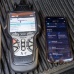
 Does My Car Have OBD2?
Unpacking the 16 Pin OBD2 Connector Pinout
The 16 pin OBD2 connector pinout, as defined by SAE J1962, is arranged in two rows of 8 pins each. Here’s a breakdown of the standard Type A connector pinout, commonly found in cars:
| Pin Number | Pin Name | Description | Typical Use |
|---|---|---|---|
| 1 | Manufacturer Discretionary | Function defined by the vehicle manufacturer. | Varies widely depending on manufacturer; often unused or for OEM specific diagnostics. |
| 2 | SAE J1850 Bus+ | Positive line for SAE J1850 PWM and VPW communication protocols. | Used in older Ford (PWM) and GM (VPW) vehicles. |
| 3 | Manufacturer Discretionary | Function defined by the vehicle manufacturer. | Varies widely; often unused or for OEM specific diagnostics. |
| 4 | Chassis Ground | Ground connection for the vehicle chassis. | Provides a common ground reference for diagnostic tools and vehicle systems. |
| 5 | Signal Ground | Signal ground for diagnostic communication. | Ensures signal integrity for data transmission between the scan tool and vehicle ECUs. |
| 6 | CAN High (J-2284) | CAN bus high signal line as per ISO 15765-4 and SAE J2284 standards. | Primary communication line for modern OBD2 systems using CAN protocol. |
| 7 | ISO 9141-2 K-Line | K-line for ISO 9141-2 and ISO 14230-4 (KWP2000) communication protocols. | Used in older European and Asian vehicles, and some Chrysler vehicles. |
| 8 | Manufacturer Discretionary | Function defined by the vehicle manufacturer. | Varies widely; often used for OEM specific diagnostics or programming. |
| 9 | Manufacturer Discretionary | Function defined by the vehicle manufacturer. | Varies widely; often used for OEM specific diagnostics, sometimes for J2534 programming voltage. |
| 10 | SAE J1850 Bus- | Negative line for SAE J1850 PWM and VPW communication protocols. | Used in older Ford (PWM) and GM (VPW) vehicles. |
| 11 | Manufacturer Discretionary | Function defined by the vehicle manufacturer. | Varies widely; often unused or for OEM specific diagnostics. |
| 12 | Manufacturer Discretionary | Function defined by the vehicle manufacturer. | Varies widely; often used for OEM specific diagnostics, sometimes for J2534 programming voltage. |
| 13 | Manufacturer Discretionary | Function defined by the vehicle manufacturer. | Varies widely; often unused or for OEM specific diagnostics. |
| 14 | CAN Low (J-2284) | CAN bus low signal line as per ISO 15765-4 and SAE J2284 standards. | Secondary communication line for modern OBD2 systems using CAN protocol, works in tandem with Pin 6. |
| 15 | ISO 9141-2 L-Line | L-line for ISO 9141-2 and ISO 14230-4 (KWP2000) communication protocols. | Used in older European and Asian vehicles, and some Chrysler vehicles, typically used in conjunction with Pin 7. |
| 16 | Battery Power | Vehicle battery positive voltage supply. | Provides power to the OBD2 scan tool, typically 12V for Type A connectors. |
Key Pin Functions Explained
- Pin 4 & 5 – Grounds: These pins provide essential ground connections. Pin 4 is chassis ground, connected to the vehicle’s frame, while Pin 5 is signal ground, providing a clean ground reference for data signals.
- Pin 6 & 14 – CAN Bus: These are the CAN High and CAN Low pins, critical for vehicles using the CAN (Controller Area Network) protocol, which is the most common protocol in modern OBD2 systems (ISO 15765-4).
- Pin 7 & 15 – ISO 9141-2 K and L Lines: These pins are used for the ISO 9141-2 and ISO 14230-4 (KWP2000) protocols, found in older vehicles, especially European and Asian models.
- Pin 16 – Battery Power: This pin supplies battery voltage (typically 12V in cars) to power the OBD2 scan tool. This allows many scan tools to operate even without their own power source.
- Pins 2 & 10 – J1850 Bus: These are for the SAE J1850 PWM and VPW protocols, used primarily in older Ford (PWM) and GM (VPW) vehicles.
- Pins 1, 3, 8, 9, 11, 12, 13 – Manufacturer Discretionary: These pins are reserved for manufacturer-specific uses. Their functions can vary greatly between vehicle brands and models, and they are often used for proprietary diagnostic or programming purposes.
OBD2 Connector Types: Type A vs. Type B
While the 16 pin OBD2 connector pinout is largely standardized, there are two main physical types: Type A and Type B. Type A is most common in cars and light-duty vehicles, while Type B is typically found in medium and heavy-duty vehicles.
The key differences are:
- Voltage: Type A connectors typically provide 12V power (Pin 16), while Type B often provides 24V.
- Physical Keying: Type B connectors have an interrupted groove in the middle, making them physically incompatible with Type A adapters. This prevents accidental connection of 12V tools to 24V systems, which could damage the tool or vehicle.
Adapters are available to convert between Type A and Type B connectors, but it’s crucial to ensure voltage compatibility when using such adapters, especially in heavy-duty applications.
OBD2 Communication Protocols and the Pinout
The OBD2 connector pinout supports several communication protocols. While modern vehicles primarily use CAN (ISO 15765-4) on pins 6 and 14, older vehicles might utilize other protocols, each associated with specific pins on the connector. The five main protocols are:
- CAN (Controller Area Network) – ISO 15765-4: Uses pins 6 (CAN High) and 14 (CAN Low). Dominant in vehicles manufactured post-2008 in the US and increasingly worldwide.
- KWP2000 (Keyword Protocol 2000) – ISO 14230-4: Typically uses pin 7 (K-line), and optionally pin 15 (L-line). Common in vehicles from the early 2000s, especially in Asia and Europe.
- ISO 9141-2: Uses pin 7 (K-line) and optionally pin 15 (L-line). Found in some European, Chrysler, and Asian vehicles from the late 1990s and early 2000s.
- SAE J1850 VPW (Variable Pulse Width Modulation): Uses pin 2 (Bus+) and pin 10 (Bus-). Primarily used in older GM vehicles.
- SAE J1850 PWM (Pulse Width Modulation): Uses pin 2 (Bus+) and pin 10 (Bus-). Primarily used in older Ford vehicles.
Understanding which protocol your vehicle uses can sometimes be inferred from which pins are populated in the OBD2 connector, although diagnostic tools typically auto-detect the protocol.
Practical Applications of OBD2 Connector Pinout Knowledge
Knowing the 16 pin OBD2 connector pinout is beneficial in several practical scenarios:
- Building Custom Diagnostic Tools: For advanced users or developers, understanding the pinout is essential for creating custom OBD2 interfaces or data logging solutions.
- Troubleshooting Connection Issues: If you’re experiencing communication problems with your scan tool, checking the pinout can help identify potential issues like bent or damaged pins.
- Wiring Adapters and Extensions: When needing to extend the OBD2 connector or adapt it for specific purposes, pinout knowledge is crucial for correct wiring.
- Educational Purposes: For students and professionals in automotive technology, understanding the OBD2 connector pinout is a fundamental aspect of learning about vehicle diagnostic systems.
Conclusion: The 16 Pin OBD2 Connector Pinout – Your Gateway to Vehicle Diagnostics
The 16 pin OBD2 connector pinout is a cornerstone of modern automotive diagnostics. Its standardization has revolutionized vehicle repair and maintenance, making it easier for professionals and enthusiasts alike to access crucial vehicle health information. By understanding the function of each pin, you gain a deeper insight into your vehicle’s diagnostic system and unlock the potential for more effective troubleshooting and maintenance. Whether you’re a seasoned mechanic or a curious car owner, knowledge of the OBD2 connector pinout is a valuable asset in navigating the complexities of today’s automotive technology.
OBD2 logger intro CANedge
Recommended for you
OBD2 DATA LOGGER: EASILY LOG & CONVERT OBD2 DATA
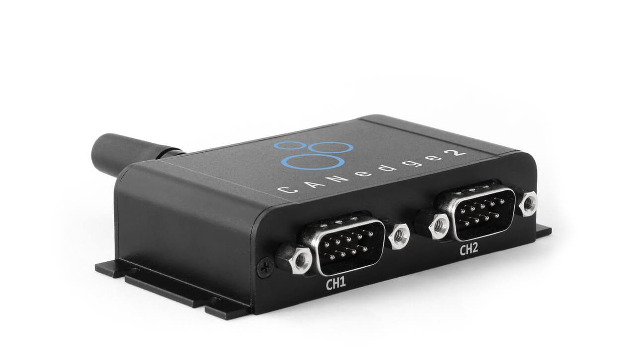 CANedge2 – Dual CAN Bus Telematics Dongle CANEDGE2 – PRO CAN IoT LOGGER
[