Understanding your vehicle’s On-Board Diagnostics (OBD2) system is crucial for modern car maintenance and repair. At the heart of this system lies the 16 Pin Obd2 Pinout, a standardized interface that allows mechanics and car enthusiasts alike to access a wealth of diagnostic information. This guide will delve into the intricacies of the 16 pin OBD2 connector, its pin assignments, and why it’s essential for anyone working with today’s vehicles.
Understanding the OBD2 Connector: The 16 Pin Interface
The OBD2 system is your car’s self-diagnostic powerhouse. It’s a standardized protocol designed to monitor and report on vehicle performance and emissions. The key to accessing this data is the OBD2 connector, a 16 pin diagnostic link connector (DLC) usually found within easy reach of the driver’s seat.
When you see the malfunction indicator light (MIL), often called the “check engine light,” it’s the OBD2 system signaling an issue. Mechanics use OBD2 scanners or readers, plugging them into this 16 pin OBD2 port, to communicate with the vehicle’s computer. This connection allows them to retrieve diagnostic trouble codes (DTCs), real-time sensor data like speed and engine temperature, and other vital information for efficient troubleshooting and repair.
Understanding OBD2: On-Board Diagnostics and the Malfunction Indicator Light (MIL) as seen when using a scan tool.
OBD2 Compatibility: Is Your Car Equipped?
The question of OBD2 compatibility is usually a simple one to answer for most modern vehicles: almost certainly, yes.
Nearly all non-electric cars manufactured in recent decades are OBD2 compliant, and many utilize the CAN bus communication protocol. However, for older vehicles, the presence of a 16 pin OBD2 connector doesn’t guarantee OBD2 support. Some older models may have the connector but lack full compliance. To ensure your vehicle is OBD2 compliant, consider the region and year it was originally purchased:
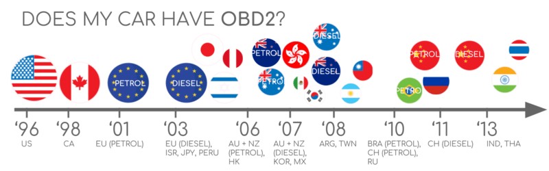
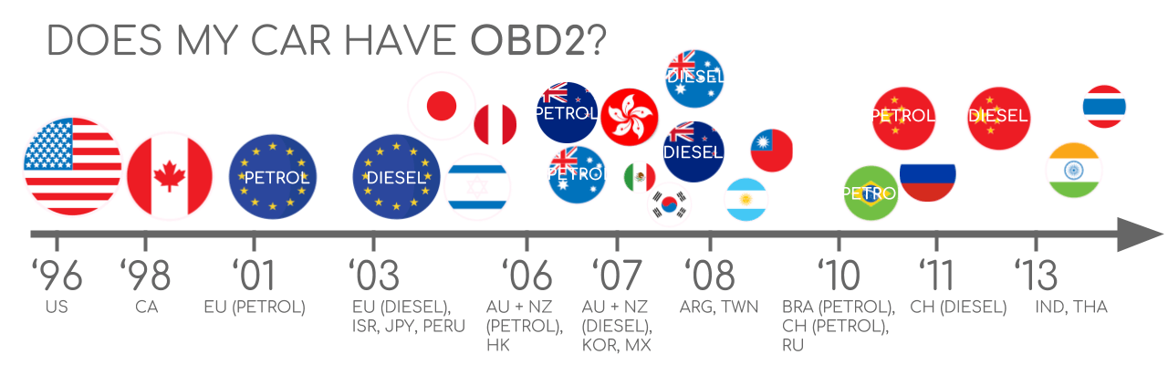 Does My Car Have OBD2?
Determining OBD2 Compliance: A guide based on purchase location and year for EU, US, and CAN market vehicles.
A Brief History of OBD2 and its Evolution
The origins of OBD2 trace back to California, driven by the California Air Resources Board (CARB). In 1991, CARB mandated OBD systems in all new vehicles sold in California for emissions monitoring.
The Society of Automotive Engineers (SAE) played a crucial role in standardizing OBD, recommending the OBD2 standard. This standardization included Diagnostic Trouble Codes (DTCs) and, importantly, a uniform OBD connector across different vehicle manufacturers, defined by SAE J1962.
The adoption of OBD2 was a phased process:
- 1996: OBD2 became mandatory in the USA for cars and light trucks.
- 2001: The European Union mandated OBD2 for gasoline-powered cars.
- 2003: The EU extended the mandate to include diesel vehicles (EOBD).
- 2005: OBD2 was required in the US for medium-duty vehicles.
- 2008: US vehicles were required to use ISO 15765-4 (CAN) as the foundation for OBD2 communication.
- 2010: OBD2 compliance became mandatory for heavy-duty vehicles in the US.
OBD2 Historical Timeline: Tracing the evolution from emission control to modern car data access via CAN bus.
OBD2 History Timeline Overview: A visual representation of the key milestones in On-Board Diagnostics development.
The Future of OBD: OBD3 and the trend towards remote diagnostics, emissions testing, cloud integration, and IoT.
The Future Landscape of OBD: OBD3 and Beyond
While OBD2 remains the standard, the automotive industry is evolving. Here’s a glimpse into the future of vehicle diagnostics:
Initially focused on emissions, legislated OBD2 is not a requirement for electric vehicles (EVs). Consequently, most modern EVs do not support standard OBD2 requests, opting instead for OEM-specific UDS communication. This shift often makes data extraction from EVs challenging, except in cases where reverse engineering has uncovered decoding methods.
Modern alternatives to OBD2 are emerging to address limitations in data richness and lower-layer protocols. These include WWH-OBD (World Wide Harmonized OBD) and OBDonUDS (OBD on UDS), both aiming to improve OBD communication by using the UDS protocol.
The concept of OBD3 envisions adding telematics to vehicles. This could involve a radio transponder in cars, enabling wireless transmission of the Vehicle Identification Number (VIN) and DTCs to a central server for automated checks. This approach could streamline emission testing and diagnostics but raises privacy concerns.
The automotive industry is also debating the role of third-party access to OBD2 data. Concerns exist about the use of OBD2 for purposes beyond repair shops, potentially creating a data-driven economy outside of manufacturer control. Proposals to limit OBD2 functionality while driving and centralize data collection by manufacturers are being discussed, driven by security concerns and the desire to control automotive data.
OBD2 Future Challenges: Electric Vehicles and the trend towards blocking third-party data access via the OBD2 connector.
Deep Dive into OBD2 Standards
OBD2 operates as a higher-layer protocol, using communication methods like CAN bus. It’s similar to other CAN-based protocols like J1939, CANopen, and NMEA 2000.
OBD2 standards comprehensively define the OBD2 connector pinout, lower-layer protocols, OBD2 parameter IDs (PIDs), and more. These standards can be categorized within the 7-layer OSI model. Notably, both SAE and ISO standards cover various layers, reflecting US (SAE) and EU (ISO) standardization efforts. Many standards are technically similar, for example, SAE J1979 and ISO 15031-5, or SAE J1962 and ISO 15031-3.
OBD2 and CAN Bus in the OSI Model: Illustrating the layered architecture with ISO 15765 and ISO 11898 standards.
The Crucial 16 Pin OBD2 Connector and SAE J1962 Standard
The 16-pin OBD2 connector, standardized under SAE J1962 / ISO 15031-3, is the physical gateway to your car’s diagnostic data. This 16 pin OBD2 port allows for easy and standardized access.
The illustration below details a typical Type A OBD2 pin connector layout, also known as the Data Link Connector (DLC).
OBD2 Connector Pinout: Type A female socket, detailing the Data Link Connector (DLC) pin assignments.
Key features of the 16 pin OBD2 connector include:
- Location: Typically found near the steering wheel, though sometimes hidden.
- Pin 16: Provides battery power, often active even when the ignition is off.
- Pinout Variability: The function of other pins depends on the communication protocol used.
- CAN Bus Dominance: CAN bus is the most prevalent lower-layer protocol, assigning pins 6 (CAN-High) and 14 (CAN-Low) as crucial communication lines.
Type A vs. Type B OBD2 Connectors: Pinout and Usage
In practice, you might encounter two main types of 16 pin OBD2 connectors: Type A and Type B. Type A is standard in cars, while Type B is more common in medium and heavy-duty vehicles.
While both types share a similar 16 pin OBD2 pinout, they differ in power supply and sometimes baud rate. Type A typically supplies 12V, whereas Type B provides 24V. Baud rates can also vary, with cars often using 500K and heavy-duty vehicles frequently using 250K (with increasing support for 500K).
Visually distinguishing them is straightforward: Type B connectors have an interrupted groove in the middle. This design allows a Type B OBD2 adapter cable to be compatible with both Type A and Type B sockets, while a Type A adapter will only fit Type A sockets.
OBD2 Connector Types A and B: Illustrating the differences in pinout, voltage (12V vs 24V), and application in cars, vans, and trucks under SAE J1962.
OBD2 and CAN Bus Integration: ISO 15765-4 Standards
Since 2008, CAN bus has been the mandated lower-layer protocol for OBD2 in US vehicles, according to ISO 15765.
ISO 15765-4, also known as Diagnostics over CAN (DoCAN), specifies how the CAN standard (ISO 11898) is used for OBD2. It standardizes the CAN interface for diagnostic equipment, focusing on the physical, data link, and network layers. Key specifications include:
- Bit-rate: Must be 250K or 500K.
- CAN IDs: Can be 11-bit or 29-bit.
- Specific CAN IDs: Designated for OBD requests and responses.
- Data Frame Length: Fixed at 8 bytes for diagnostic CAN frames.
- Adapter Cable Length: Maximum length of 5 meters.
OBD2 vs. CAN bus ISO15765: Highlighting the relationship and standards governing OBD2 communication over CAN bus.
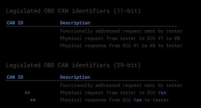
OBD2 CAN Identifiers: 11-bit and 29-bit Explained
OBD2 communication over CAN bus relies on request and response message exchanges.
In most passenger vehicles, 11-bit CAN IDs are used for OBD2. The ‘Functional Addressing’ ID, 0x7DF, is used to query all OBD2-compliant ECUs for data on a requested parameter. ‘Physical Addressing’ requests, using CAN IDs 0x7E0-0x7E7, can target specific ECUs but are less common.
ECUs respond using 11-bit IDs in the range 0x7E8-0x7EF. The most frequent response ID is 0x7E8 (Engine Control Module, ECM), followed by 0x7E9 (Transmission Control Module, TCM).
Some vehicles, particularly vans and medium to heavy-duty vehicles, may utilize 29-bit extended CAN identifiers for OBD2 communication. The ‘Functional Addressing’ CAN ID in this case is 0x18DB33F1. Corresponding responses use CAN IDs ranging from 0x18DAF100 to 0x18DAF1FF, with typical examples being 0x18DAF110 and 0x18DAF11E. These response IDs are also sometimes represented in ‘J1939 PGN’ format, specifically PGN 0xDA00 (55808), which J1939-71 standard designates as ‘Reserved for ISO 15765-2’.
OBD2 Protocol Request and Response Frames: Illustrating the structure of PID data and parameters within OBD2 communication.
 OBD2 OBD CAN bus Identifiers 7DF 7E8 7E0
OBD2 CAN bus Identifiers Overview: Table showing common CAN bus IDs like 7DF, 7E8, and 7E0 used in OBD2 communication.
OBD2 vs. Proprietary CAN Protocols: Understanding the Difference
It’s important to understand that vehicle ECUs operate using OEM-specific CAN protocols, independent of OBD2. These proprietary CAN protocols are unique to vehicle brands, models, and years. Interpreting this OEM-specific data is generally not possible without OEM tools or reverse engineering.
Connecting a CAN bus data logger to your car’s 16 pin OBD2 connector might capture OEM-specific CAN data, often broadcast at high rates (1000-2000 frames/second). However, many newer vehicles employ a ‘gateway’ that restricts access to this data, allowing only OBD2 communication through the OBD2 port.
Think of OBD2 as a secondary, standardized protocol running alongside the OEM-specific protocol. It’s designed for diagnostics and emissions monitoring, while the OEM protocol manages the vehicle’s core functions.
OBD2 vs. Proprietary CAN bus Data: Comparing standardized OBD2 data with OEM-specific CAN bus data in vehicle communication.
Bit-rate and ID Validation in OBD2 Communication
OBD2 over CAN uses either 250K or 500K bit-rates and 11-bit or 29-bit CAN IDs, leading to four possible combinations. Modern cars commonly use 500K with 11-bit IDs. Diagnostic tools should systematically validate these parameters.
ISO 15765-4 provides a procedure for initialization to determine the correct combination. This process relies on the mandatory support for a specific OBD2 request (mode 0x01 PID 0x00) in OBD2-compliant vehicles and the occurrence of CAN error frames when using an incorrect bit-rate.
Newer versions of ISO 15765-4 consider OBD communication via OBDonUDS in addition to OBDonEDS. While this article primarily focuses on OBDonEDS (OBD2, SAE OBD, EOBD, ISO OBD as per ISO 15031-5/SAE J1979), WWH-OBD/OBDonUDS (OBD on Unified Diagnostic Service as per ISO 14229, ISO 27145-3/SAE J1979-2) is increasingly relevant, especially in EU trucks and buses.
Protocol testing (OBDonEDS vs OBDonUDS) can involve sending UDS requests with 11-bit/29-bit functional address IDs for service 0x22 and data identifier (DID) 0xF810 (protocol identification). OBDonUDS-compliant vehicles should have ECUs that respond to this DID.
OBD2 Bit-rate and CAN ID Validation Flow: A flowchart illustrating the process defined in ISO 15765-4 for systematic validation.
Five Lower-Layer OBD2 Protocols: Beyond CAN
While CAN (ISO 15765) is now dominant, older vehicles (pre-2008) may use one of four other lower-layer protocols for OBD2. Understanding these can be helpful when diagnosing older cars. The 16 pin OBD2 pinout can sometimes provide clues as to the protocol in use.
- ISO 15765 (CAN bus): Mandatory in US cars since 2008 and widely used today.
- ISO14230-4 (KWP2000): Common in 2003+ Asian vehicles.
- ISO 9141-2: Used in EU, Chrysler, and Asian cars (2000-2004).
- SAE J1850 (VPW): Primarily used in older GM vehicles.
- SAE J1850 (PWM): Primarily used in older Ford vehicles.
OBD2 Five Protocols: CAN (ISO 15765), KWP2000, SAE J1850, and ISO 9141, showcasing the range of lower-layer protocols.
ISO-TP for OBD2 Messaging: Handling Larger Data
OBD2 messages on CAN bus are transported using ISO-TP (ISO 15765-2), a transport protocol enabling payloads larger than 8 bytes. This is essential for OBD2 functions like retrieving the VIN or DTCs. ISO 15765-2 manages segmentation, flow control, and reassembly of these larger messages.
For smaller OBD2 data packets that fit within a single CAN frame, ISO 15765-2 specifies ‘Single Frame’ (SF) usage. Here, the first data byte (PCI field) indicates payload length, leaving 7 bytes for OBD2 communication.
ISO 15765-2 ISO-TP OBD2 Frame Types: Diagram illustrating Single Frame (SF), First Frame (FF), Consecutive Frame (CF), and Flow Control (FC) types.
Dissecting the OBD2 Diagnostic Message: SAE J1979, ISO 15031-5
To understand OBD2 communication on CAN, let’s examine a ‘Single Frame’ OBD2 CAN message. An OBD2 message includes an identifier, data length (PCI field), and data. The data itself is structured into Mode, Parameter ID (PID), and data bytes.
OBD2 PIDs Message Structure: Breakdown of an OBD-II message structure, explaining Mode, PID, ID, and data bytes.
OBD2 Request and Response Example: Vehicle Speed
Consider an example of requesting and receiving vehicle speed data.
A diagnostic tool sends a request message with CAN ID 0x7DF and 2 payload bytes: Mode 0x01 and PID 0x0D (for Vehicle Speed). The vehicle responds with CAN ID 0x7E8 and 3 payload bytes, including the speed value in the 4th byte, 0x32 (decimal 50).
Using OBD2 PID decoding rules for PID 0x0D, we interpret 0x32 as 50 km/h.
OBD2 Request and Response Example: Showing request ID 7DF and response ID 7E8 for vehicle speed parameter.
OBD2 PID Example: Vehicle Speed PID 0D, illustrating the data bytes and their interpretation.
The 10 Standard OBD2 Services (Modes)
OBD2 defines 10 diagnostic services, also referred to as modes. Mode 0x01 provides real-time data, while others handle DTCs, freeze frame data, and more.
Vehicles aren’t required to support all 10 OBD2 modes and may include OEM-specific modes beyond these standard ones. In OBD2 messages, the mode is the 2nd byte. In requests, the mode is directly included (e.g., 0x01), and in responses, 0x40 is added to the mode value (e.g., resulting in 0x41 for a mode 0x01 response).
OBD2 Services and Modes: Overview of the 10 OBD2 PID modes including current data, freeze frame, and DTC clearing.
OBD2 Parameter IDs (PIDs): Accessing Specific Data
Within each OBD2 mode are Parameter IDs (PIDs). For example, mode 0x01 contains approximately 200 standardized PIDs for real-time data like speed, RPM, and fuel level. However, vehicles typically support only a subset of these PIDs.
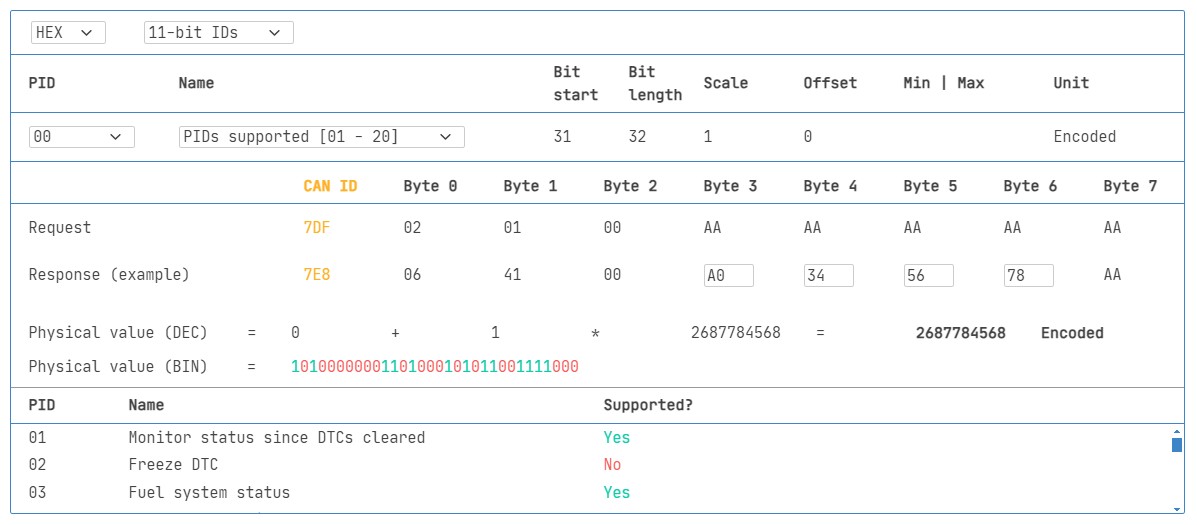
PID 0x00 in mode 0x01 is particularly significant. If an emissions-related ECU supports any OBD2 services, it must support mode 0x01 PID 0x00. Responding to this PID, the ECU indicates support for PIDs 0x01-0x20. This makes PID 0x00 useful as a fundamental OBD2 compatibility test. Similarly, PIDs 0x20, 0x40, and so on, determine support for subsequent mode 0x01 PIDs.
OBD2 Protocol Request and Response Frames: Again illustrating PID data and parameter structure in OBD2 communication.
OBD2 PID Overview Tools and Resources
SAE J1979 and ISO 15031-5 appendices provide scaling information for standard OBD2 PIDs, enabling conversion of raw data to physical values. Online tools and resources are also available to simplify PID lookup and interpretation.
 OBD2 PID overview tool
OBD2 PID Overview Tool: Interface of a tool for service 01, aiding in OBD2 PID lookup and interpretation.
Practical Guide: Logging and Decoding OBD2 Data
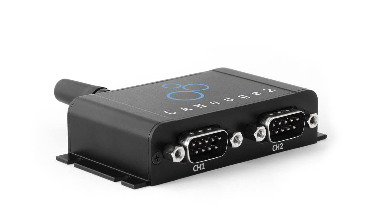
Let’s explore a practical example of logging OBD2 data using a CANedge CAN bus data logger. The CANedge allows configuration of custom CAN frames for transmission, making it suitable for OBD2 logging.
Connecting the CANedge to your vehicle is straightforward using an OBD2-DB9 adapter cable.
OBD2 PID Data Logger Request: Depicting the request process using IDs 7df and 7e8 for PID data logging.
 OBD2 bit rate test Validating Bit Rate: Testing CAN frame transmission at 500K to validate bit rate.
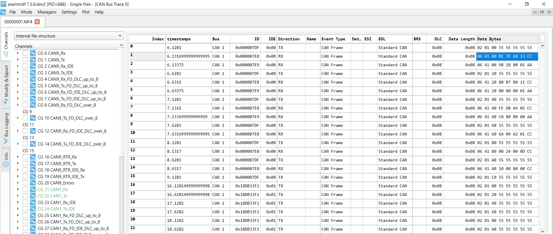 OBD2 Supported PIDs Test Supported PIDs Test Responses: Reviewing responses to ‘Supported PIDs’ test in asammdf.
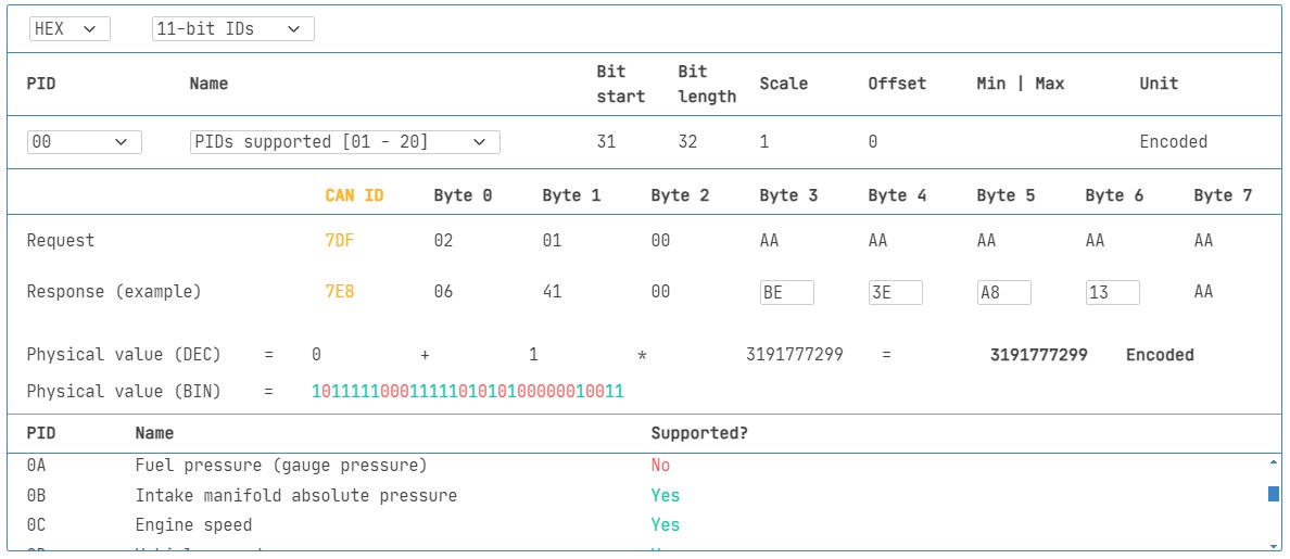 Review supported PIDs via OBD2 lookup tool
Step-by-Step: Testing Bit-rate, IDs, and Supported PIDs
ISO 15765-4 outlines how to determine the bit-rate and IDs for a specific vehicle. Here’s how to test using CANedge:
- Bit-rate Test: Send a CAN frame at 500K and check for successful transmission. If unsuccessful, try 250K.
- Bit-rate Confirmation: Use the validated bit-rate for subsequent communication.
- Supported PIDs Request: Send ‘Supported PIDs’ requests and analyze the responses.
- ID Type Determination: Response IDs indicate 11-bit vs. 29-bit IDs.
- PID Support Discovery: Response data reveals supported PIDs.
Most post-2008 non-EV vehicles support 40-80 PIDs using 500K bit-rate, 11-bit CAN IDs, and the OBD2/OBDonEDS protocol. Multiple responses to a single OBD request (using 0x7DF) are common, as this ID polls all ECUs. ECM ECU (0x7E8) often supports all PIDs supported by other ECUs, suggesting efficiency gains by targeting requests directly to this ECU using ‘Physical Addressing’ CAN ID 0x7E0.
Configuring OBD2 PID Requests for Data Logging
Once you’ve identified supported PIDs, bit-rate, and CAN IDs, configure your data logger to request specific PIDs of interest. Consider these points:
- CAN IDs: Switch to ‘Physical Addressing’ request IDs (e.g., 0x7E0) to minimize redundant responses.
- Request Spacing: Introduce 300-500 ms intervals between requests to avoid overwhelming ECUs.
- Power Management: Use triggers to halt transmissions when the vehicle is inactive to prevent battery drain.
- Data Filtering: Implement filters to record only OBD2 responses, especially if OEM-specific CAN data is also present.
With these configurations, your logger is set to record raw OBD2 data efficiently.
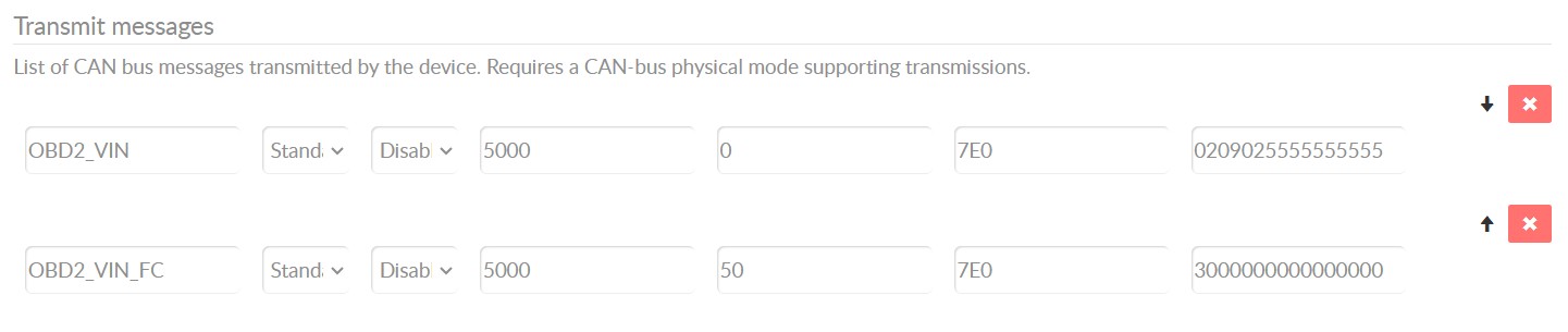
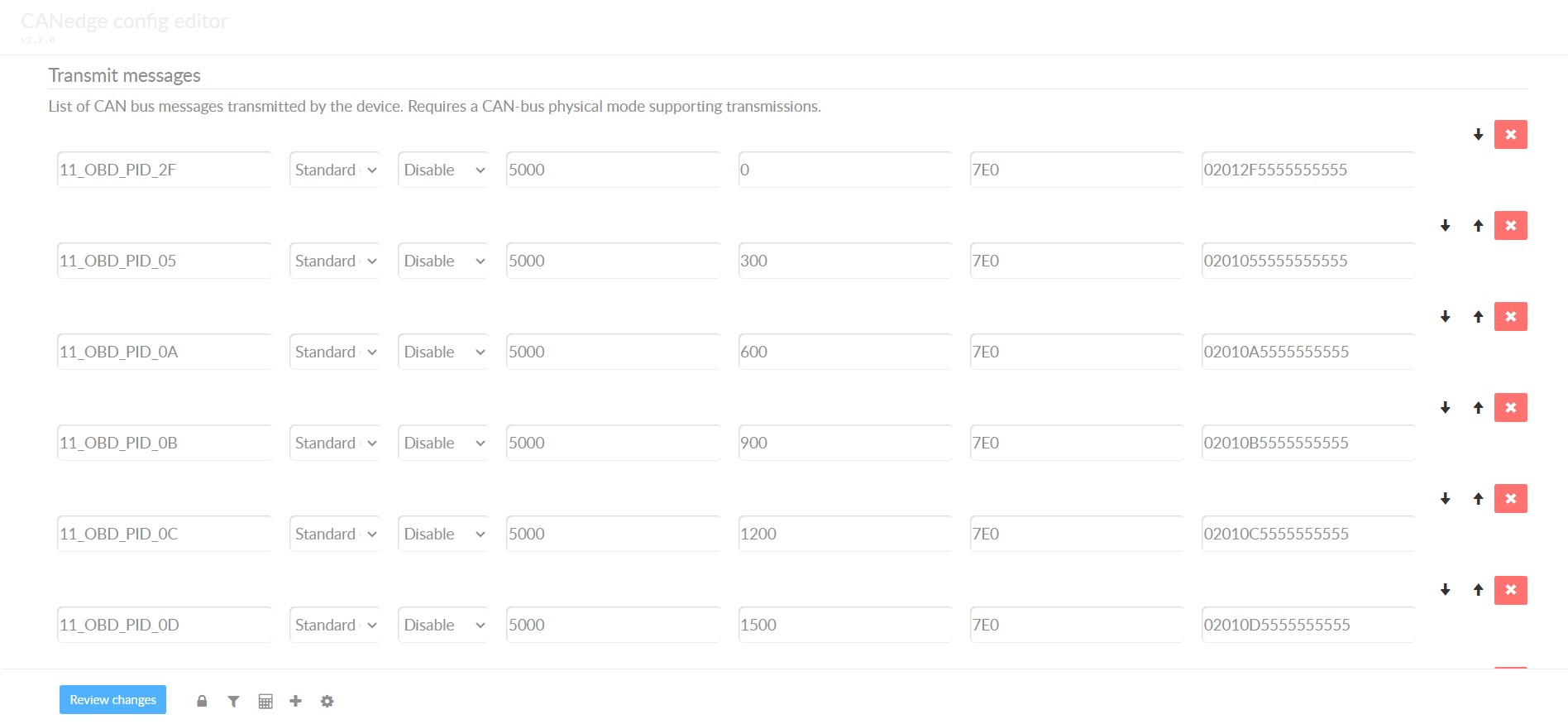 obd2-transmit-list-example-canedge CANedge OBD2 PID Request List: Example transmit list showing configured requests for OBD2 PIDs.
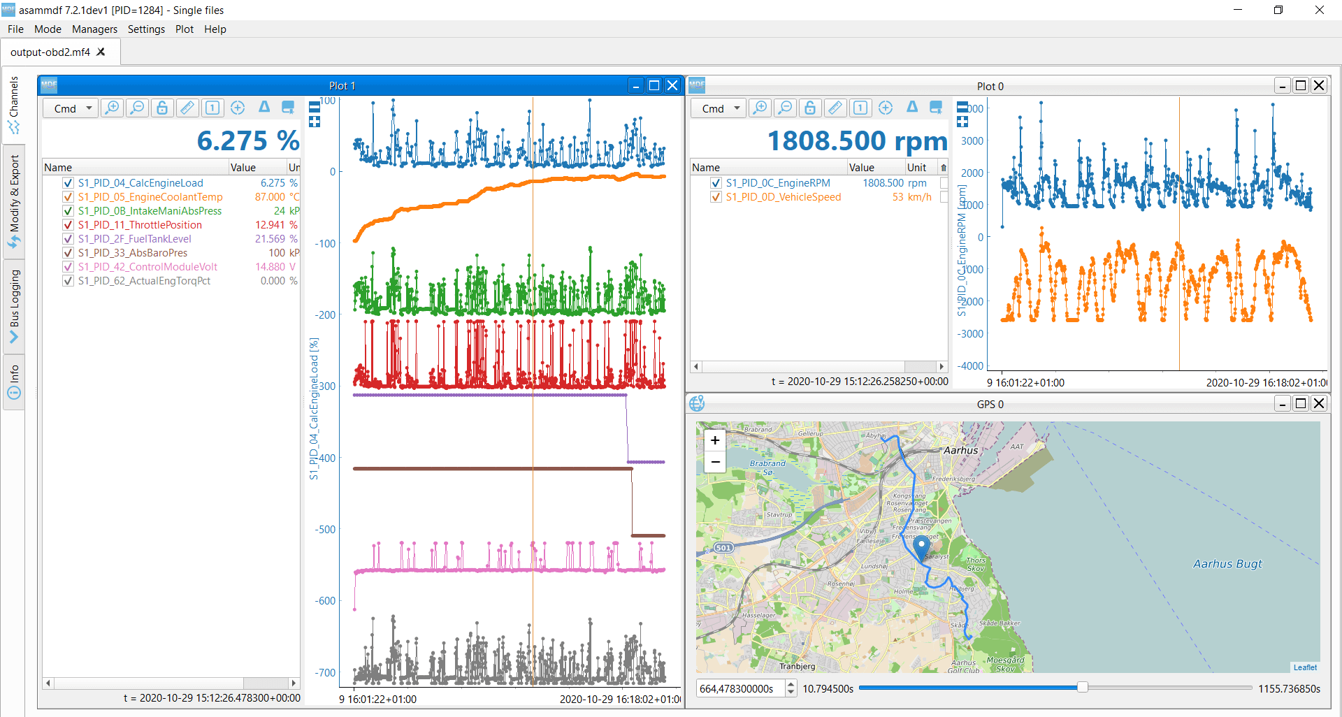 OBD2 data decoded visual plot asammdf CAN bus DBC file Decoded OBD2 Data Plot: Visual representation of decoded OBD2 data using asammdf and a CAN bus DBC file.
DBC Decoding of Raw OBD2 Data: Making Sense of the Logs
To analyze and visualize logged OBD2 data, you need to decode it into physical values. Decoding information is in ISO 15031-5/SAE J1979 and accessible through online resources. A free OBD2 DBC file simplifies DBC decoding in CAN bus software tools.
Decoding OBD2 data is more complex than standard CAN signal decoding because OBD2 PIDs share CAN IDs (e.g., 0x7E8). CAN ID alone is insufficient to identify signals. You must use CAN ID, OBD2 mode, and PID to uniquely identify signals. This ‘extended multiplexing’ is handled in DBC files.
CANedge as an OBD2 Data Logger: Streamlined Data Recording
The CANedge CAN bus data logger is designed for easy OBD2 data recording to SD cards (8-32 GB). Connect it to your vehicle’s 16 pin OBD2 port to start logging and use free software/APIs with our OBD2 DBC for decoding.
Multi-Frame OBD2 Communication Examples with ISO-TP
While many OBD2 interactions are single-frame, multi-frame communication is necessary for larger data exchanges. ISO-TP (ISO 15765-2) manages this, requiring flow control frames. In practice, a static flow control frame can be transmitted shortly after the initial request.
Software tools that support ISO-TP, like CANedge MF4 decoders, are needed for handling multi-frame OBD2 responses.
 OBD2-multi-frame-request-message-vehicle-identification-number
OBD2 Multi-Frame Request Message: Example of a multi-frame request for Vehicle Identification Number (VIN).
Example 1: Retrieving Vehicle Identification Number (VIN) via OBD2
Retrieving the VIN using OBD2 mode 0x09 and PID 0x02 involves multi-frame communication.
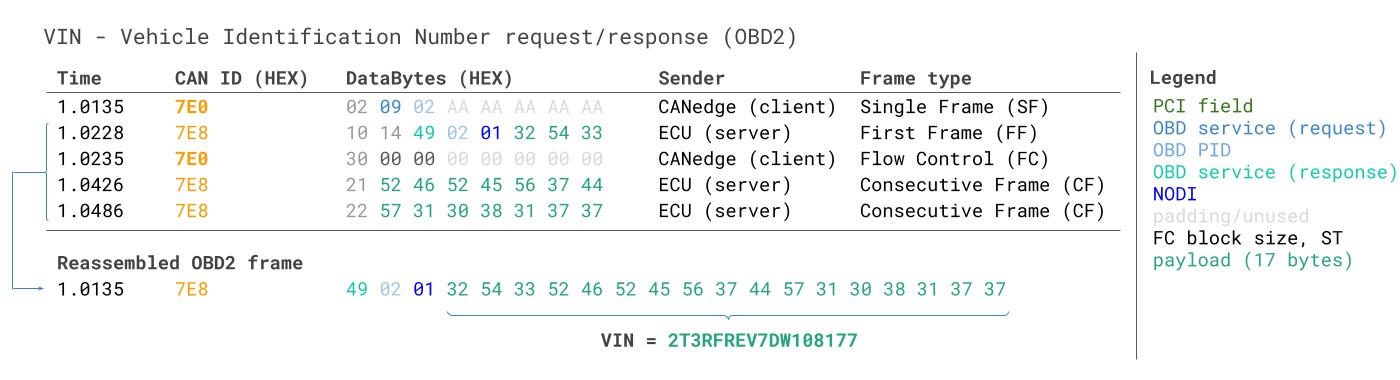 VIN Vehicle Identification Number OBD2 Example multi-frame
VIN Retrieval via OBD2: Example of multi-frame communication for Vehicle Identification Number (VIN) retrieval.
The diagnostic tool sends a Single Frame request with PCI field (0x02), service identifier (0x09), and PID (0x02). The vehicle responds with a First Frame containing PCI, length, mode (0x49), and PID (0x02). Following the PID is the Number Of Data Items (NODI) and then 17 bytes for the VIN, which can be converted from HEX to ASCII.
Example 2: Multi-PID Request (6x) in OBD2
OBD2 allows requesting up to 6 mode 0x01 PIDs in a single request frame. The ECU responds with data for supported PIDs, possibly using multi-frame responses. While efficient, this method complicates generic DBC file use due to signal encoding specific to the request.
 Requesting multiple PIDs in one request
Multi-PID Request Example: Requesting multiple PIDs in a single OBD2 request frame, showing an ISO-TP trace.
Multi-frame responses in this scenario include requested PIDs and their data. Decoding these responses with generic DBC files is challenging. While custom scripts can interpret responses based on request messages, this approach is complex for large-scale applications.
Example 3: Diagnostic Trouble Codes (DTCs) via OBD2
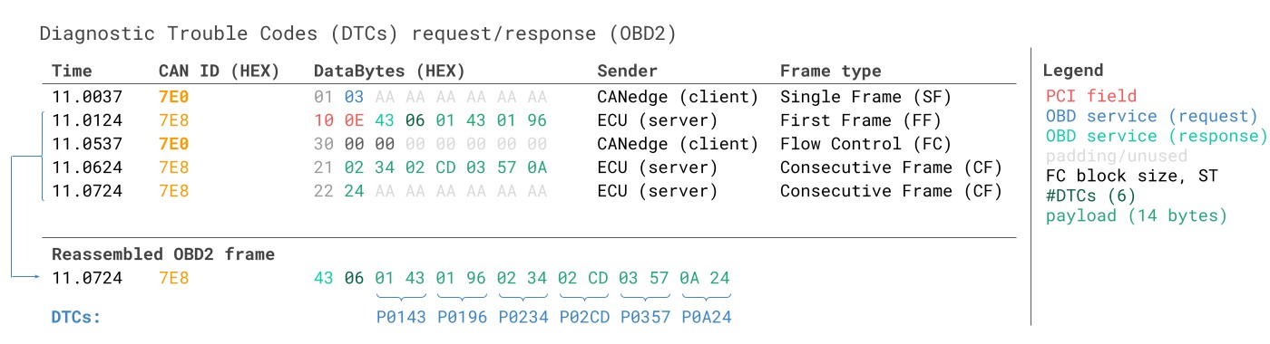
OBD2 mode 0x03 is used to request emissions-related DTCs. The request contains only the mode (0x03). ECUs respond with the number of stored DTCs and the DTCs themselves, each DTC being 2 bytes. Multi-frame responses are necessary if more than 2 DTCs are stored.
OBD2 DTC Decoding: Example of Diagnostic Trouble Code (DTC) decoding and DBC interpretation.
 OBD2 Diagnostic Trouble Codes DTC CAN Bus Request Response Example
OBD2 DTC Request and Response: CAN bus trace example of requesting and receiving Diagnostic Trouble Codes (DTCs).
The 2-byte DTC value is categorized and includes a 4-digit hexadecimal code. Decoded DTC values can be looked up using OBD2 DTC lookup tools.
OBD2 Data Logging: Real-World Use Cases
OBD2 data logging has diverse applications across various sectors:
OBD2 Data Logger Applications: On-board diagnostics and data logging use cases for cars and vehicles.
Vehicle Data Logging for Cars
OBD2 data is valuable for reducing fuel costs, improving driving habits, testing prototype components, and insurance telematics.
OBD2 Real-time Streaming Diagnostics: Using OBD2 interfaces for real-time data streaming via USB for vehicle diagnostics.
Real-time Car Diagnostics
OBD2 interfaces enable real-time streaming of human-readable diagnostic data, aiding in immediate vehicle issue diagnosis.
OBD2 Predictive Maintenance: Leveraging OBD2 data loggers for predictive maintenance and telematics in IoT applications.
Predictive Maintenance Applications
Cloud-connected IoT OBD2 loggers can monitor vehicles for predictive maintenance, helping prevent breakdowns.
Vehicle Black Box Logger: OBD2 loggers as ‘black boxes’ in vehicles for insurance, warranty, and diagnostic purposes.
Vehicle Black Box Functionality
OBD2 loggers can act as vehicle ‘black boxes,’ providing crucial data for dispute resolution and diagnostics.
Do you have an OBD2 data logging application in mind? Contact us for expert consultation!
Want to master CAN bus and OBD2?
Download our comprehensive ‘Ultimate Guide’ PDF for in-depth knowledge.
Ready to log or stream OBD2 data?
Get your OBD2 data logger today!
Further Reading
OBD2 DATA LOGGER: EASILY LOG & CONVERT OBD2 DATA
 CANedge2 – Dual CAN Bus Telematics Dongle CANEDGE2 – PRO CAN IoT LOGGER
CAN BUS INTERFACE: STREAMING OBD2 DATA WITH SAVVYCAN