Engine swaps can be a thrilling upgrade for your ride, but navigating the intricacies of vacuum lines and coolant hoses, especially in older OBD2 systems like those found in 1996 Hondas with B18B1 engines, can quickly become a headache. Many enthusiasts encounter confusion when dealing with these connections, particularly when swapping in different B-series engines. Let’s break down some common points of confusion and shed light on your 1996 B18b1 Obd2 Vacuum Diagram, helping you ensure your swap is smooth and your engine runs right.
Understanding Coolant Line Connections on Your B18B1
One of the most common areas of concern during an engine swap is the coolant system. Getting the hoses routed correctly is crucial to prevent overheating and ensure proper engine cooling. On the B18B1, and similar B-series engines, you’ll find several coolant inlets and outlets that need to be correctly identified and connected.
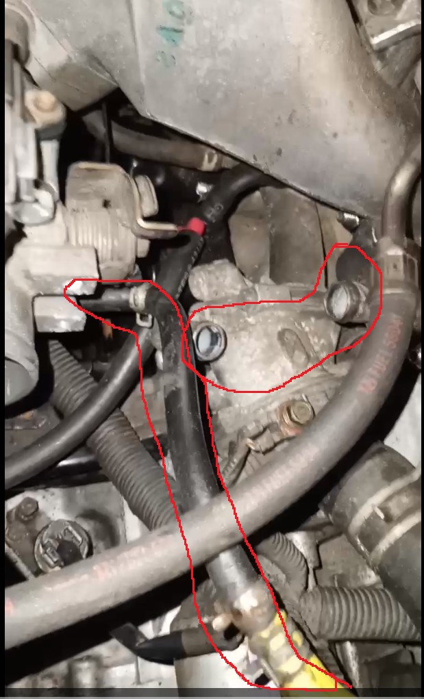 Coolant inlet/outlet locations on a B-series engine
Typically, you’ll find connections near the thermostat housing and around the rear of the engine block, close to the firewall. The thermostat housing usually has both an inlet and an outlet. One hose will connect to the radiator’s upper hose, carrying hot coolant away from the engine, while another connects to the lower radiator hose, returning cooled coolant to the engine block. The connections at the rear of the engine often involve heater core hoses and potentially connections to an intake manifold coolant passage if your setup includes one. Referencing a 1996 B18B1 OBD2 vacuum diagram, though it primarily focuses on vacuum lines, can sometimes offer clues about general hose routing and component locations, indirectly aiding in coolant line identification.
Then there are additional smaller hoses. Often, a smaller hose near the main coolant lines will lead to the coolant overflow tank. This hose isn’t under pressure but allows coolant to expand out of the radiator and be drawn back in as the system cools, maintaining proper coolant levels.
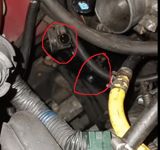 Lower coolant hose connections near the transmission mount
Navigating Vacuum Line Connections for OBD2 B18B1
Vacuum lines are equally critical for proper engine function. They control various systems, including fuel pressure regulation, emissions controls, and brake boosters. A 1996 B18B1 OBD2 vacuum diagram is your best friend here. This diagram will illustrate all vacuum lines, their source (usually the intake manifold or throttle body), and their destination (various vacuum-operated components).
Common vacuum line connections include:
- Intake Manifold to Fuel Pressure Regulator: This line provides manifold vacuum to the fuel pressure regulator, adjusting fuel pressure based on engine load.
- Intake Manifold to Brake Booster: A larger diameter vacuum hose runs to the brake booster, providing vacuum assist for power brakes.
- Throttle Body to EVAP Purge Solenoid: Vacuum lines are part of the Evaporative Emission Control System (EVAP), and a line will typically run from the throttle body area to the EVAP purge solenoid.
- PCV Valve: The Positive Crankcase Ventilation (PCV) valve is another vacuum-operated component, usually connected to the intake manifold to draw crankcase gases for combustion.
Without a proper 1996 B18B1 OBD2 vacuum diagram, you might misconnect lines, leading to vacuum leaks, poor engine performance, and potentially triggering OBD2 fault codes. Always consult the specific vacuum diagram for your engine and chassis combination.
Identifying Electrical Connectors During Your Swap
Beyond hoses, electrical connectors can also cause confusion. When swapping engines, you’ll encounter various connectors that need to be correctly mated to the chassis harness.
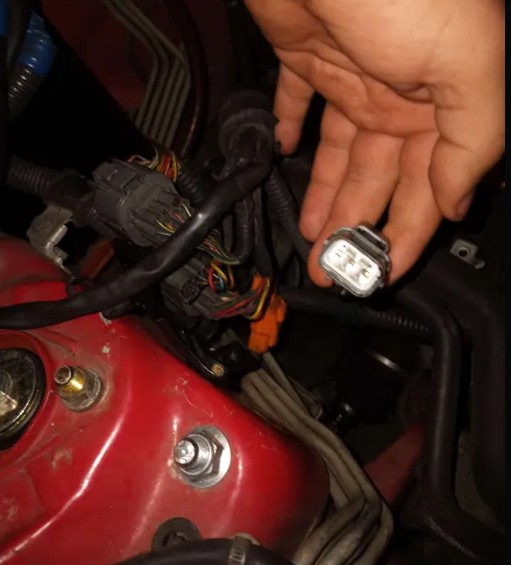 Unidentified electrical connectors near the ECU
Common connector locations and potential points of confusion include:
- Alternator Connectors: Typically, you’ll find connectors near the alternator for its various functions. These might include power, ground, and signal wires.
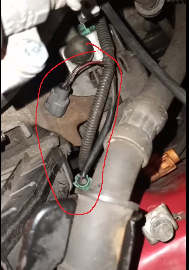 Grey and green connectors near the alternator
- Throttle Body Connectors: Connectors around the throttle body are for sensors like the Throttle Position Sensor (TPS) and potentially the Idle Air Control Valve (IACV), depending on your specific B18B1 setup.
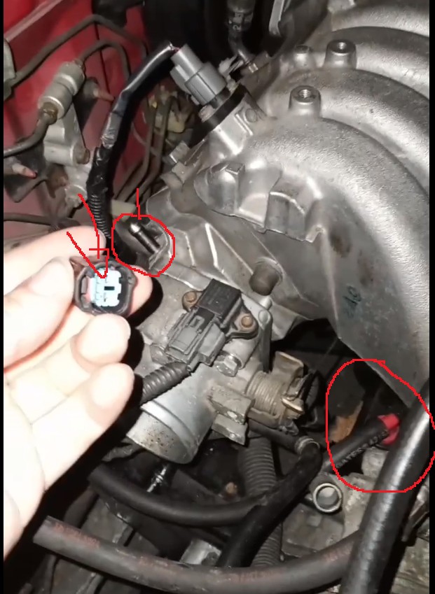 Connector above the throttle body
- ECU Connectors: The Engine Control Unit (ECU) connectors are crucial. You need to ensure the engine harness connectors properly interface with your chassis harness at the ECU location. Sometimes, engine swaps require adapter harnesses or repinning of connectors to ensure compatibility.
If you find yourself with unmatched connectors, double-check your engine harness and chassis harness compatibility. A wiring diagram for both your engine and chassis is invaluable in these situations. You may need to consult wiring diagrams to determine the function of each wire and connector to ensure proper connections.
Conclusion
Successfully completing an engine swap, especially when dealing with older OBD2 systems and vacuum lines, hinges on meticulous attention to detail and accurate information. A 1996 B18B1 OBD2 vacuum diagram isn’t just a helpful tool; it’s essential. Combined with careful tracing of coolant lines and methodical identification of electrical connectors, you can confidently navigate your engine swap and get your Honda running smoothly. When in doubt, always consult repair manuals, wiring diagrams, and online communities dedicated to Honda engine swaps for specific guidance and support.