Understanding the fuse box layout in your 2003 Ford F-150 is crucial for maintaining its electrical system. Fuses protect your vehicle’s circuits from overloads, and knowing their locations and functions can save you time and money when troubleshooting electrical issues. This guide provides detailed fuse box diagrams for your 2003 Ford F-150, ensuring you can quickly identify the right fuse for systems potentially related to your OBD2 port and other components. This year model of the Ford F-150 is equipped with two distinct fuse boxes, each serving different sets of circuits. Let’s explore their locations and fuse configurations to help you keep your truck running smoothly.
Passenger Compartment Fuse Box Diagram
The passenger compartment fuse panel in your 2003 Ford F-150 is located inside the vehicle. This fuse box houses fuses and relays that control various interior functions and some engine management components. Consult the diagram and table below to pinpoint the fuse you need.
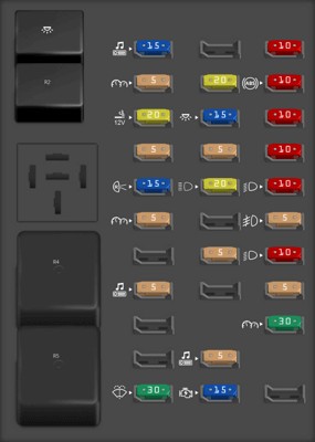 Passenger compartment fuse panel diagram of the 2003 Ford F-150, detailing interior electrical circuits.
| Type | No. | Description |
|---|---|---|
| Fuse MINI 15A | 1 | Audio |
| Fuse MINI 5A | 2 | Powertrain Control Module (PCM), Cluster |
| Fuse MINI 20A | 3 | Cigar lighter, Data link connector |
| Fuse MINI 5A | 4 | Power mirror switch, Mirror turn signal relays |
| Fuse MINI 15A | 5 | Speed control module, Reverse lamp, Climate mode switch, Daytime Running Lamps (DRL) relay, Digital Transmission Range (DTR) sensor |
| Fuse MINI 5A | 6 | Cluster, Brake shift interlock solenoid, GEM |
| Fuse MINI 5A | 8 | Radio, Remote entry module, GEM, In-vehicle entertainment system (SuperCrew only) |
| Fuse MINI 30A | 11 | Front washer pump relay, Wiper run/park relay, Wiper HI/LO relay, Windshield wiper motor |
| Fuse MINI 20A | 13 | Stop lamp switch (Lamps), Turn/Hazard flasher |
| Fuse MINI 15A | 14 | Battery saver relay, Interior lamp relay |
| Fuse MINI 5A | 15 | Stop lamp switch (speed control, brake shift interlock), GEM, Rear Anti-lock Brake System (RABS) module |
| Fuse MINI 20A | 16 | Headlamps (hi beams), Cluster (hi beam indicator) |
| Fuse MINI 5A | 18 | Instrument illumination (dimmer switch power) |
| Fuse MINI 5A | 20 | Audio, GEM, PCM, Transmission range sensor |
| Fuse MINI 15A | 21 | DTR sensor, Clutch switch, Starter relay, I/P fuse 20 |
| Fuse MINI 10A | 22 | Air bag module, Passenger air bag deactivation module |
| Fuse MINI 10A | 23 | Trailer tow battery Charge relay, Turn/Hazard flasher, 4×4 solenoids, 4×4 relays, Overhead console, 4-Wheel Anti-lock Brake System (4WABS) module, EC mirror, Heated seats |
| Fuse MINI 10A | 24 | Function selector switch assembly |
| Fuse MINI 10A | 25 | Heated mirrors |
| Fuse MINI 10A | 26 | Right-hand low beam headlamp |
| Fuse MINI 5A | 27 | Foglamp relay and foglamp indicator, Main light switch (upstream) |
| Fuse MINI 10A | 28 | Left-hand low beam headlamp |
| Fuse MINI 5A | 29 | Autolamp module, Transmission overdrive control switch, Central security module, Beltminder |
| Fuse MINI 30A | 30 | Passive Anti-theft transceiver, Cluster, Ignition coils, PCM relay, Coil on plugs, Radio noise capacitor, ECC diode |
| Relay | R1 | Interior lamp relay |
| Relay | R2 | Battery saver relay |
| Relay | R4 | One-touch down window relay |
| Relay | R5 | Accessory delay relay |
Power Distribution Box Diagram
The power distribution box in the 2003 Ford F-150 is located in the engine compartment. This box contains fuses and relays for high-current circuits and engine-related systems. If you are experiencing issues with engine performance or exterior lighting, this is the fuse box to check first.
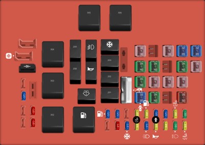 Power distribution box diagram of the 2003 Ford F-150, illustrating engine and high-current electrical components.
| Type | No. | Description |
|---|---|---|
| Fuse MINI 20A | 1 | Power point |
| Fuse MINI 30A | 2 | Powertrain Control Module (PCM) |
| Fuse MINI 30A | 3 | Main light switch, Headlamp relay, Multifunction switch |
| Fuse MINI 20A | 4 | Console power point [Harley Davidson only] |
| Fuse MINI 20A | 5 | Trailer tow back-up/park lamps |
| Fuse MINI 15A | 6 | Main light switch, Park lamp relay |
| Fuse MINI 20A | 7 | Horn |
| Fuse MINI 15A | 8 | Power door locks, Central Security Module (CSM), Lock relays [not used on SuperCrew] |
| Fuse MINI 15A | 9 | Daytime Running Lamps (DRL), Fog lamps |
| Fuse MINI 20A | 10 | Fuel pump |
| Fuse MINI 20A | 11 | Alternator field |
| Fuse MINI 20A | 12 | Rear auxiliary power point [SuperCrew only] |
| Fuse MINI 15A | 13 | A/C clutch |
| Fuse MINI 10A | 15 | Running board lamps |
| Fuse MINI 15A | 16 | Bi-fuel injector module, fuel selector switch and alternative fuel injectors [Bi-fuel vehicles only] |
| Fuse MINI 15A | 18 | PCM, Fuel injectors, Fuel pump relay, Mass air flow sensor |
| Fuse MINI 10A | 19 | Trailer/Camper adapter (right stop/turn lamp) |
| Fuse MINI 10A | 20 | Trailer/Camper adapter (left stop/turn lamp) |
| Fuse MINI 15A | 23 | HEGO sensor, Automatic transmission |
| Fuse FMX/JCase 30A | 101 | Trailer tow battery charge |
| Fuse FMX/JCase 20A | 102 | Four-wheel Anti-lock Brake System (4WABS) module/Rear-wheel Anti-lock Brake System (RABS) module, Ignition switch |
| Fuse FMX/JCase 50A | 103 | Central junction box |
| Fuse FMX/JCase 30A | 104 | 4×4 shift motor & clutch |
| Fuse FMX/JCase 40A | 105 | Climate control front blower |
| Fuse FMX/JCase 20A | 106 | Intercooler pump [supercharged engine only] |
| Fuse FMX/JCase 30A | 108 | Trailer tow electric brake |
| Fuse FMX/JCase 30A | 110 | Accessory delay relay [Not used on SuperCrew] |
| Fuse FMX/JCase 40A | 111 | Ignition switch battery feed (start and run circuits) |
| Fuse FMX/JCase 30A | 112 | Drivers power seat, Adjustable pedal switch |
| Fuse FMX/JCase 40A | 113 | Ignition switch battery feed (run and accessory circuits) |
| Fuse FMX/JCase 20A | 115 | Power door locks [SuperCrew only] |
| Fuse FMX/JCase 40A | 116 | Heated backlight |
| Fuse FMX/JCase 40A | 117 | Audiophile radio [SuperCrew only] |
| Fuse FMX/JCase 30A | 118 | Heated seats |
| Relay | 201 | Trailer tow park lamp relay |
| Relay | 202 | Front wiper run/park relay |
| Relay | 203 | Trailer tow backup lamp relay |
| Relay | 204 | A/C clutch relay |
| Relay | 205 | Horn relay |
| Relay | 206 | Fog lamp relay |
| Relay | 207 | Front washer pump relay |
| Relay | 208 | Intercooler pump relay [supercharged engine only] |
| Relay | 209 | Front wiper HI/LO relay |
| Relay | 301 | Fuel pump relay |
| Relay | 302 | Trailer tow battery charge relay |
| Relay | 303 | Heated backlight relay [SuperCrew only] |
| Relay | 304 | PCM relay |
| Relay | 305 | Fuel pump HI/LO relay [supercharged engine only] |
| Relay | 306 | Inertia switch relay [supercharged engine only] |
| Diode ATO | 501 | PCM diode |
| Diode ATO | 502 | A/C compressor diode |
| Circuit breaker MAXI | 601 | Power windows, Moonroof [SuperCrew only] |
For diagnosing issues potentially related to your OBD2 system, it’s important to note that the Data Link Connector, used for OBD2 access, is often powered through fuses in the passenger compartment fuse box. Specifically, fuse number 3 (20A) in the passenger compartment is listed for the “Cigar lighter, Data link connector”. If you are having trouble connecting your OBD2 scanner, checking this fuse is a good first step.
By utilizing these diagrams and fuse descriptions, you can effectively troubleshoot electrical problems in your 2003 Ford F-150. Remember to always consult your vehicle’s owner manual for the most accurate and up-to-date information and to ensure you are using the correct replacement fuses.