The 2004 Lincoln Aviator, a luxury SUV known for its blend of comfort and capability, incorporates a complex electrical system that relies on fuses to protect its various components. Understanding the fuse system, especially the OBD2 fuse, is crucial for any Aviator owner for diagnostics and maintenance. This guide will delve into the fuse box locations, diagrams, and specifically focus on the 2004 Lincoln Aviator Obd2 Fuse, providing you with comprehensive information to keep your vehicle running smoothly.
Understanding Fuse Boxes in Your 2004 Lincoln Aviator
Like most modern vehicles, the 2004 Lincoln Aviator utilizes multiple fuse boxes strategically placed throughout the vehicle. These fuse boxes house fuses and relays that safeguard different circuits from overloads and potential damage. Knowing the location of these fuse boxes is the first step in diagnosing and resolving electrical issues. For the 2004 Aviator, you can typically find fuse panels in the following locations:
Passenger Compartment Fuse Box
The primary fuse box inside the passenger compartment is located under the instrument panel, to the left of the steering column. Accessing this panel is usually straightforward, often requiring you to simply locate and remove a cover panel. This fuse box is responsible for protecting circuits related to interior functions, such as the radio, lighting, power windows, and importantly, the OBD2 port.
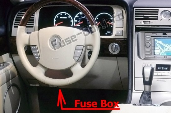 Passenger compartment fuse box location in a 2003-2005 Lincoln Aviator, situated under the instrument panel to the left of the steering column.
Engine Compartment Fuse Box
For circuits related to the engine and other critical vehicle systems, the engine compartment fuse box is the place to look. In the 2004 Lincoln Aviator, this fuse box is situated in the engine compartment. This box typically houses fuses for systems like the engine control unit (ECU), fuel pump, cooling fan, and exterior lighting.
Additional Relay Boxes
Beyond the main fuse boxes, the 2004 Aviator also includes auxiliary and rear relay boxes. The auxiliary relay box in this model year is also located in the engine compartment. The rear relay box is positioned on the rear passenger side quarter trim panel. Accessing the rear relay box might require professional assistance from a dealer or certified technician.
2004 Lincoln Aviator Fuse Box Diagrams
To effectively utilize the fuse boxes, diagrams are essential. These diagrams provide a clear layout of each fuse and relay, along with their corresponding amperage ratings and descriptions. Below are the fuse box diagrams specifically for the 2004 Lincoln Aviator.
Instrument Panel Fuse Box Diagram (2004)
This diagram details the fuses located in the passenger compartment fuse box. It’s crucial for identifying fuses related to interior electronics and the OBD2 port.
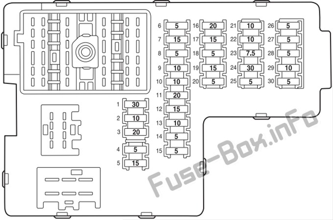 Diagram of the instrument panel fuse box in a 2004 Lincoln Aviator, illustrating the position and function of each fuse.
Instrument Panel Fuse Assignment (2004)
| # | Amp Rating | Description |
|---|---|---|
| 1 | 30A | Moonroof motor, Driver seat lumbar switch |
| 2 | 10A | VAPS module, Memory seat module, Body security module, Tire Pressure Monitor System (TPMS), Sunload/Autolamp sensor (SecuriLock LED) |
| 3 | 20A | Radio, Navigation system |
| 4 | 5A | Front wiper module |
| 5 | 15A | Flasher relay (turn/hazards) |
| 6 | 5A | Electronic Hidden Antenna Module (EHAM) (antenna amplifier), Radio, Moonroof motor, Driver window motor, Navigation |
| 7 | 15A | Heated mirrors, DEATC module |
| 8 | 5A | Daytime Running Lamps (DRL) module, Heated PCV valve |
| 9 | 10A | Back-up lamps (DTRS), Electrochromatic mirror |
| 10 | 10A | Heated backlight relay coil, Climate seat modules, Auxiliary A/C temperature blend/mode actuator, A/C clutch relay contact |
| 11 | 20A | Not used (spare) |
| 12 | 15A | Restraints module |
| 13 | 10A | Brake shift interlock |
| 14 | 5A | Not used (spare) |
| 15 | 5A | Instrument cluster, Rear wiper module, TPMS |
| 16 | 20A | Cigar lighter, OBD II |
| 17 | 15A | Delayed accessory relay coil, Battery saver relay coil and contacts |
| 18 | 5A | Not used (spare) |
| 19 | 15A | Washer pump |
| 20 | 5A | Shifter, Clock, Power mirror switch, DVD |
| 21 | 10A | Brake pressure switch (ABS), IVD switch, Flasher relay |
| 22 | 10A | ABS module |
| 23 | 7.5A | Liftgate release relay coil and contacts |
| 24 | 30A | Subwoofer, Navigation |
| 25 | 5A | Trailer tow battery charge relay coil |
| 26 | 5A | SecuriLock transceiver |
| 27 | 5A | Rear park assist, VAPS module |
| 28 | 5A | Radio, Navigation |
| 29 | 10A | DTRS, Feed to Fuse 28 |
| 30 | 5A | Instrument cluster, Compass module, Auxiliary A/C relay coil |
Engine Compartment Fuse Box Diagram (2004)
This diagram outlines the fuses in the engine bay fuse box, protecting vital engine and system components.
Engine Compartment Fuse Assignment (2004)
| # | Amp Rating | Description |
|---|---|---|
| 1 | 60A | Power Junction Box (PJB) |
| 2 | 30A | Door locks (BSM) |
| 3 | — | Not used |
| 4 | 40 A | Heated backlight/mirrors |
| 5 | 40 A | Anti-lock Brake System (ABS) module (pump) |
| 6 | 60A | Delayed accessory |
| 7 | 20A | Daytime Running Lamps (DRL) module |
| 8 | 20A | Electric cooling fan |
| 9 | 20A | Headlamp switch |
| 10 | 30A | ABS module (valves) |
| 11 | 40A | PTEC relay contacts |
| 12 | 50A | Ignition/Starter relay |
| 13 | 40 A | Trailer tow relays |
| 14 | 15 A | Brake lamp feed |
| 15 | 10A | Keep alive power (PTEC/cluster/DEATC) |
| 16 | 20A | Power point #3 |
| 17 | 20A | Rear wiper module |
| 18 | 20A | 4×4 module |
| 19 | 30A | Driver window motor |
| 20 | 30A | Electric trailer brakes |
| 21 | 30A | Memory seat module |
| 22 | 20A | Main exterior lamps (low beam headlamps, high beam headlamps, fog lamps) |
| 23 | 30A | Ignition switch |
| 24 | 20A | Horn relay |
| 25 | 20A | Power point #1 |
| 26 | 20A | Fuel pump relay contacts |
| 27 | 20A | Trailer tow lamps |
| 28 | 20A | Power point #2 |
| 29 | 60A | PJB |
| 30 | 30A | Front wiper module |
| 31 | 30A | Climate-controlled seats modules |
| 32 | 30A | Passenger seat switch |
| 33 | 30A | Auxiliary blower motor |
| 34 | 20A | Right HID relay |
| 35 | 20A | Left HID relay |
| 36 | 40 A | Blower motor |
| 37 | 15 A | A/C clutch relay, TXV, Transmission, Speed control |
| 38 | 15 A | HEGO, VMV, Canister vent, IMCC-LSRC, EGR module |
| 39 | 15 A | Injectors |
| 40 | 15 A | PTEC, Mass Air Flow (MAF) sensor, Fuel pump relay |
| 41 | 25A | Coil on plug, PTEC relay |
| 42 | 10A | Right low beam (halogen) |
| 43 | 10A | Left low beam (halogen) |
| 44 | 2A | Heated PCV valve (w/DRL only) |
| 45 | 2A | Brake Pressure Switch |
| 46 | 20A | High beams/Fog lamps |
| 47 | — | Horn relay |
| 48 | — | Fuel pump relay |
| 49 | — | High beam relay |
| 50 | — | Fog lamp relay |
| 51 | — | Not used |
| 52 | — | A/C clutch relay |
| 53 | — | Trailer tow right turn relay |
| 54 | — | Trailer tow left turn relay |
| 55 | — | Blower motor relay |
| 56 | — | Starter motor relay |
| 57 | — | PTEC relay |
| 58 | — | Ignition relay |
| 59 | — | Driver brake applied relay |
| 60 | — | PCM diode |
| 61 | — | A/C clutch diode |
| 62 | 30A | Power windows (Circuit breaker) |
Auxiliary Relay Box Diagram (2004)
This diagram shows the relays within the auxiliary relay box in the engine compartment.
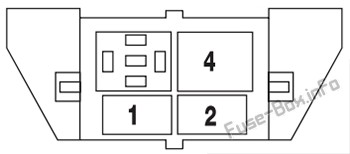 Diagram of the auxiliary relay box in a 2004 Lincoln Aviator, detailing the relays for HID headlights and EDF.
Auxiliary Relay Box Assignment (2004)
| Relay # | Description |
|---|---|
| 1 | Left HID relay (1/2 ISO) |
| 2 | Right HID relay (1/2 ISO) |
| 3 | Open |
| 4 | EDF relay (Full ISO) |
Rear Relay Box Diagram (2004)
This diagram illustrates the relays located in the rear relay box, often related to trailer towing and liftgate functions.
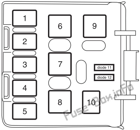 Rear relay box diagram for 2003-2005 Lincoln Aviator models, indicating relays for liftgate release and trailer towing.
Rear Relay Box Assignment (2004)
| Relay # | Description |
|---|---|
| 1 | Liftgate release solenoid |
| 2 | Open |
| 3 | Open |
| 4 | Trailer tow back-up lamps |
| 5 | Open |
| 6 | Open |
| 7 | Trailer tow battery charge |
| 8 | Trailer tow park lamps |
| 9 | Open |
| 10 | 2003: Puddle lamps 2004-2005: Open |
| Diode 11 | Open |
| Diode 12 | Open |
Focus on the OBD2 Fuse in Your 2004 Lincoln Aviator
For 2004 Lincoln Aviator owners, locating the OBD2 fuse is often a primary concern when dealing with diagnostic issues. The OBD2 port (On-Board Diagnostics II) is essential for connecting scan tools to read vehicle data and diagnose problems. If your OBD2 scanner is not powering up when connected to your Aviator, a blown OBD2 fuse is a likely culprit.
Locate the OBD2 Fuse:
Referring to the Instrument Panel Fuse Box Diagram for the 2004 Lincoln Aviator, you will find the OBD2 fuse at position #16.
Fuse #16 Details:
- Amp Rating: 20A
- Description: Cigar lighter, OBD II, Liftgate release relay coil and contacts.
Function and Importance:
This fuse not only protects the OBD2 port but also the cigar lighter (power outlet) and the liftgate release relay. If you are experiencing issues with any of these systems in addition to your OBD2 port, checking fuse #16 should be your first step. A blown fuse here can prevent communication with your vehicle’s computer, hindering any diagnostic efforts.
Troubleshooting and Replacing Fuses
If you suspect a blown fuse, follow these steps for troubleshooting and replacement:
- Identify the Symptoms: Determine which systems are not working. For OBD2 issues, no power to your scan tool is a key symptom.
- Locate the Fuse Box: Refer to the diagrams and descriptions above to find the correct fuse box. For the OBD2 fuse, it’s the Instrument Panel Fuse Box.
- Pinpoint the Fuse: Using the fuse box diagram, locate fuse #16 (20A) for the OBD2 port.
- Inspect the Fuse: Visually inspect the fuse. A blown fuse typically has a broken wire inside or appears burnt. You can also use a fuse tester for confirmation.
- Replace the Fuse: If the fuse is blown, replace it with a new fuse of the exact same amperage rating (20A). Using a fuse with a higher amperage can damage the circuit.
- Test the System: After replacement, check if the affected systems (OBD2 port, cigar lighter, liftgate release) are now functioning correctly.
Important Notes:
- Always use the correct amperage fuse.
- If the fuse blows again immediately after replacement, it indicates a more significant underlying electrical problem that requires professional diagnosis.
- Keep spare fuses of various amperage ratings in your vehicle for emergencies.
By understanding the fuse box layout and specifically knowing the location and function of the 2004 Lincoln Aviator OBD2 fuse, you can effectively troubleshoot common electrical issues and maintain your vehicle with greater confidence. Remember to always consult your vehicle’s owner’s manual for the most accurate and up-to-date information.
For more detailed guides on fuse checking and replacement, as well as understanding why fuses blow, explore our additional resources:
Learn how to check fuses effectively.
Discover the steps to replace a blown fuse in your car.
Understand the common reasons behind car fuses blowing.
Explore the different types of automotive fuses available.