Understanding your 2005 Ford F-150’s fuse box is crucial for diagnosing and resolving electrical issues. Locating the correct fuse and understanding its function can save you time and money on potential repairs. While the term “OBD2 fuse location” might lead you to expect a dedicated fuse box solely for the OBD2 system, it’s more about identifying which fuse in your F-150’s electrical system powers the OBD2 port and related diagnostic components. This guide will walk you through the fuse box locations in your 2005 F-150 and pinpoint fuses relevant to the OBD2 system and general vehicle operation.
Fuse Box Locations on a 2005 Ford F-150
Your 2005 Ford F-150 is equipped with not one, but three fuse boxes, each serving different circuits throughout your vehicle. Knowing where each is located is the first step to troubleshooting any electrical problem, including issues that might impact your OBD2 diagnostic port. These locations are:
- Passenger Compartment Fuse Panel: This is likely the most frequently accessed fuse box, located inside the cabin of your F-150.
- Auxiliary Relay Box (with DRL): Some 2005 F-150 models include Daytime Running Lights (DRL). If your truck has DRL, it will have this auxiliary box.
- Auxiliary Relay Box (without DRL): For models without Daytime Running Lights, a slightly different auxiliary relay box configuration is used.
Let’s explore each of these locations in detail with diagrams and fuse listings to help you find the “OBD2 fuse location” you might be looking for, or any other fuse in your 2005 F-150.
Passenger Compartment Fuse Panel Diagram
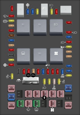
The passenger compartment fuse panel, often the primary fuse box for many interior and essential vehicle functions, is located within the cabin of your 2005 F-150. Consult the diagram below to understand the layout and identify specific fuse positions.
 Passenger Compartment Fuse Panel Diagram in a 2005 Ford F-150
This fuse box controls a wide range of functions. Notably, for OBD2 relevance, fuse #41 (20A) is listed as “Cigar lighter, Diagnostic connector power”. This fuse is the most likely candidate you’re looking for when considering the “2005 F150 Obd2 Fuse Location” as it directly powers the diagnostic connector, which includes your OBD2 port.
Here’s a detailed listing of the fuses within the Passenger Compartment Fuse Panel:
| Type | No. | Description |
|---|---|---|
| Fuse MINI 10A | 1 | Run/Accessory – Wipers, Instrument cluster |
| Fuse MINI 20A | 2 | Stop/Turn lamps, Speed control deactivate switch |
| Fuse MINI 5A | 3 | Power mirrors, Memory logic power, Memory seats and pedals |
| Fuse MINI 10A | 4 | DVD battery power, Power fold mirror |
| Fuse MINI 7.5A | 5 | Keep alive memory for Powertrain Control Module (PCM) and climate control module |
| Fuse MINI 15A | 6 | Parklamps, BSM, Instrument panel illumination |
| Fuse MINI 5A | 7 | Radio (start signal) |
| Fuse MINI 10A | 8 | Heated mirrors, Switch indicator |
| Fuse MINI 20A | 10 | Trailer tow back-up lamps relay (PCB1), Trailer tow parklamp relay (R201) |
| Fuse MINI 10A | 11 | A/C clutch, 4×4 solenoid |
| Fuse MINI 10A | 13 | Climate control module power, Flasher relay |
| Fuse MINI 10A | 14 | With a yellow sticker on the back of the fuse panel: Back-up lamp and Daytime Running Lamps (DRL) relay coil, A/C pressure switch, ABS, Heated PCV [5.4L], Redundant speed control switch All others: Back-up lamp and Daytime Running Lamps (DRL) relay coil, A/C pressure switch, Redundant speed control switch, Heated PCV [5.4L], Trailer tow back-up lamps relay coil, ABS, Reverse park aid, EC mirror |
| Fuse MINI 5A | 15 | Overdrive cancel, Cluster, Brake-Shift Interlock (BSI) |
| Fuse MINI 10A | 16 | Brake-shift interlock solenoid |
| Fuse MINI 15A | 17 | Fog lamp relay (R202) |
| Fuse MINI 10A | 18 | Run/Start feed – Overhead power point, Electrochromatic mirror, Heated seats, BSM, Compass, RSS (Reverse Sensing System) |
| Fuse MINI 10A | 19 | Restraints (Air bag module) |
| Fuse MINI 10A | 20 | Battery feed for overhead power point |
| Fuse MINI 15A | 21 | Cluster keep alive power |
| Fuse MINI 10A | 22 | Delayed accessory power for audio, power door lock switch and moonroof switch illumination |
| Fuse MINI 10A | 23 | RH low beam headlamp |
| Fuse MINI 15A | 24 | Battery saver power for demand lamps |
| Fuse MINI 10A | 25 | LH low beam headlamp |
| Fuse MINI 20A | 26 | Horn relay (PCB3), Horn power |
| Fuse MINI 5A | 27 | Passenger Air bag Deactivation (PAD) warning lamp, Cluster air bag warning lamp, Cluster RUN /START power |
| Fuse MINI 5A | 28 | SecuriLock transceiver (PATS) |
| Fuse MINI 15A | 29 | PCM 4×4 power |
| Fuse MINI 15A | 30 | PCM 4×4 power |
| Fuse MINI 20A | 31 | Radio power |
| Fuse MINI 15A | 32 | Vapor Management Valve (VMV), A/C clutch relay, Canister vent, Heated Exhaust Gas Oxygen (HEGO) sensors #11 and #21, CMCV, Mass Air Flow (MAF) sensor, VCT, Heated Positive Crankcase Ventilation (PCV) valve [4.2L engine], CID sensor [4.2L engine] |
| Fuse MINI 15A | 33 | Shift solenoid, CMS #12 and #22 |
| Fuse MINI 20A | 34 | Fuel injectors and PCM power, Intake Manifold Runner Control [4.2L engine] |
| Fuse MINI 20A | 35 | Instrument cluster high beam indicator, High beam headlamps |
| Fuse MINI 10A | 36 | Trailer tow right turn/stop lamps |
| Fuse MINI 20A | 37 | Rear power point |
| Fuse MINI 25A | 38 | Subwoofer power |
| Fuse MINI 20A | 39 | Instrument panel power point |
| Fuse MINI 20A | 40 | Low beam headlamps, DRL |
| Fuse MINI 20A | 41 | Cigar lighter, Diagnostic connector power |
| Fuse MINI 10A | 42 | Trailer tow left turn/stop lamps |
| Fuse FMX/JCase 30A | 101 | Starter solenoid |
| Fuse FMX/JCase 20A | 102 | Ignition switch feed |
| Fuse FMX/JCase 20A | 103 | ABS valves |
| Fuse FMX/JCase 30A | 105 | Electric trailer brakes |
| Fuse FMX/JCase 30A | 106 | Trailer tow battery charge |
| Fuse FMX/JCase 30A | 107 | Power door locks (BSM) |
| Fuse FMX/JCase 30A | 108 | Passenger power seat |
| Fuse FMX/JCase 30A | 109 | Driver power seat, Adjustable pedals |
| Fuse FMX/JCase 30A | 111 | 4×4 relays |
| Fuse FMX/JCase 40A | 112 | ABS pump power |
| Fuse FMX/JCase 30A | 113 | Wipers and washer pump |
| Fuse FMX/JCase 40A | 114 | Heated backlite, Heated mirror power |
| Fuse FMX/JCase 30A | 116 | Blower motor |
| Fuse FMX/JCase 30A | 118 | Heated seats |
| Circuit breaker MAXI | 401 | Power windows, Moonroof, Power sliding backlite |
| Relay | R01 | Starter solenoid |
| Relay | R02 | Accessory delay |
| Relay | R03 | Hi-beam headlamps |
| Relay | R04 | Heated backlite |
| Relay | R05 | Trailer tow battery charge |
| Relay | R06 | Blower motor |
| Relay | R201 | Trailer tow park lamps |
| Relay | R202 | Fog lamps |
| Relay | R203 | PCM |
Auxiliary Relay Box (with DRL) Diagram
If your 2005 Ford F-150 is equipped with Daytime Running Lights (DRL), you will find this auxiliary relay box. This box is in addition to the passenger compartment fuse panel and handles circuits related to DRL and other systems.
 Auxiliary Relay Box Diagram with DRL in a 2005 Ford F-150
Here is the fuse and relay listing for the Auxiliary Relay Box (with DRL):
| Type | No. | Description |
|---|---|---|
| Fuse ATO 5A | F03 | Clockspring illumination |
| Relay | R01 | 4×4 CCW |
| Relay | R02 | 4×4 CW |
| Relay | R03 | Daytime Running Lamps (DRL) high beam disable |
| Relay | R201 | (DRL) Daytime running lights |
| Relay | R202 | (A/C clutch) A/C magnetic clutch |
| Diode ATO | D01 | (A/C clutch) A/C magnetic clutch |
Auxiliary Relay Box (without DRL) Diagram
For 2005 Ford F-150 models that do not have Daytime Running Lights, the auxiliary relay box configuration is slightly different. Refer to the diagram below for the layout of this fuse box.
 Auxiliary Relay Box Diagram without DRL in a 2005 Ford F-150
Below is the fuse and relay information for the Auxiliary Relay Box (without DRL):
| Type | No. | Description |
|---|---|---|
| Fuse ATO 5A | F03 | Clockspring illumination |
| Diode ATO | D01 | A/C clutch |
| Relay | R202 | A/C clutch |
Conclusion
When searching for the “2005 f150 obd2 fuse location”, you’re most likely looking for Fuse #41 (20A) “Diagnostic connector power” in the Passenger Compartment Fuse Panel. This fuse provides power to your OBD2 diagnostic port. If you are experiencing issues with your OBD2 scanner not powering up or connecting, checking this fuse should be one of your first steps.
Remember to always consult your 2005 Ford F-150 owner’s manual for the most accurate fuse diagrams and locations, as variations can occur. Understanding your fuse box layouts is essential for maintaining your vehicle’s electrical system and performing basic troubleshooting.
