Understanding your 2005 Ford F-150’s fuse box is crucial for diagnosing and resolving electrical issues, especially when it comes to using your OBD2 scanner. Locating the correct fuse for your OBD2 port is a common need for many F-150 owners. This guide will walk you through the fuse box locations and diagrams for your 2005 Ford F-150, specifically pinpointing the fuse related to the diagnostic connector and other essential fuses.
Your 2005 Ford F-150 is equipped with multiple fuse boxes, each playing a vital role in protecting your truck’s electrical circuits. Knowing where these fuse boxes are and what fuses they contain is the first step in troubleshooting electrical problems, including issues that might prevent your OBD2 scanner from working correctly. Let’s dive into the locations and diagrams to help you find the “2005 Ford F150 Obd2 Fuse Location” and other relevant fuses.
Understanding the Fuse Boxes in Your 2005 Ford F-150
The 2005 Ford F-150 utilizes a system of fuse boxes and relay boxes to manage and protect its complex electrical system. Fuses are designed to break the circuit and stop the flow of electricity if there’s an overload, preventing damage to components. For your 2005 F-150, there are primarily three main fuse box locations you need to be aware of:
- Passenger Compartment Fuse Panel: This fuse box is located inside the vehicle, typically under the dashboard on the driver’s side. It houses fuses for many of the interior and convenience features of your F-150.
- Auxiliary Relay Box (with DRL): Some 2005 Ford F-150 models are equipped with Daytime Running Lights (DRL). If your truck has DRL, it will have an auxiliary relay box, usually found in the engine compartment.
- Auxiliary Relay Box (without DRL): For 2005 F-150 models without Daytime Running Lights, there’s also an auxiliary relay box, located in the engine compartment, but with a slightly different configuration compared to the DRL version.
Locating the Fuse Boxes on a 2005 Ford F-150
To effectively find the “2005 ford f150 obd2 fuse location”, you’ll need to access these fuse boxes. Here’s how:
1. Passenger Compartment Fuse Panel / Power Distribution Box
This is your primary fuse box for interior functions and is also where you’ll find the fuse related to your OBD2 diagnostic connector. It’s generally located beneath the left side of the instrument panel. You may need to lie on your back and look upwards under the dashboard to locate it.
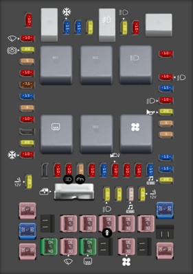
 2005 Ford F-150 fuse box diagram Passenger compartment fuse panel / power distribution box
Passenger compartment fuse panel diagram for a 2005 Ford F-150, highlighting its role in interior electrical functions and the location of the diagnostic connector fuse.
2. Auxiliary Relay Box (with DRL) & (without DRL)
Both auxiliary relay boxes are situated in the engine compartment. Their exact location can slightly vary, but they are generally found on the driver’s side, near the firewall or the battery. You’ll recognize them as black plastic boxes with labels indicating “Fuses” or “Relays.”
 2005 Ford F-150 fuse box diagram Auxiliary relay box (with DRL)
Diagram of the auxiliary relay box with DRL for a 2005 Ford F-150, showing the arrangement of relays and fuses specific to models equipped with daytime running lights.
 2005 Ford F-150 fuse box diagram Auxiliary relay box (without DRL)
Auxiliary relay box diagram for 2005 Ford F-150 models without DRL, illustrating the fuse and relay layout for vehicles not equipped with daytime running lights.
2005 Ford F-150 Fuse Diagrams and Charts
Once you’ve located the fuse boxes, you’ll need to understand the fuse diagrams to find the specific “2005 ford f150 obd2 fuse location” or any other fuse you need to check. Below are the fuse charts for each of the fuse boxes mentioned.
Passenger Compartment Fuse Panel Diagram
This table details the fuses and relays within the passenger compartment fuse panel. Notably, Fuse #41 (20A) is listed as “Cigar lighter, Diagnostic connector power.” This is the fuse you’ll want to check if you’re experiencing issues with your OBD2 scanner not powering up or connecting.
| Type | No. | Description |
|---|---|---|
| Fuse MINI 10A | 1 | Run/Accessory – Wipers, Instrument cluster |
| Fuse MINI 20A | 2 | Stop/Turn lamps, Speed control deactivate switch |
| Fuse MINI 5A | 3 | Power mirrors, Memory logic power, Memory seats and pedals |
| Fuse MINI 10A | 4 | DVD battery power, Power fold mirror |
| Fuse MINI 7.5A | 5 | Keep alive memory for Powertrain Control Module (PCM) and climate control module |
| Fuse MINI 15A | 6 | Parklamps, BSM, Instrument panel illumination |
| Fuse MINI 5A | 7 | Radio (start signal) |
| Fuse MINI 10A | 8 | Heated mirrors, Switch indicator |
| Fuse MINI 20A | 10 | Trailer tow back-up lamps relay (PCB1), Trailer tow parklamp relay (R201) |
| Fuse MINI 10A | 11 | A/C clutch, 4×4 solenoid |
| Fuse MINI 10A | 13 | Climate control module power, Flasher relay |
| Fuse MINI 10A | 14 | With a yellow sticker on the back of the fuse panel: Back-up lamp and Daytime Running Lamps (DRL) relay coil, A/C pressure switch, ABS, Heated PCV [5.4L], Redundant speed control switch All others: Back-up lamp and Daytime Running Lamps (DRL) relay coil, A/C pressure switch, Redundant speed control switch, Heated PCV [5.4L], Trailer tow back-up lamps relay coil, ABS, Reverse park aid, EC mirror |
| Fuse MINI 5A | 15 | Overdrive cancel, Cluster, Brake-Shift Interlock (BSI) |
| Fuse MINI 10A | 16 | Brake-shift interlock solenoid |
| Fuse MINI 15A | 17 | Fog lamp relay (R202) |
| Fuse MINI 10A | 18 | Run/Start feed – Overhead power point, Electrochromatic mirror, Heated seats, BSM, Compass, RSS (Reverse Sensing System) |
| Fuse MINI 10A | 19 | Restraints (Air bag module) |
| Fuse MINI 10A | 20 | Battery feed for overhead power point |
| Fuse MINI 15A | 21 | Cluster keep alive power |
| Fuse MINI 10A | 22 | Delayed accessory power for audio, power door lock switch and moonroof switch illumination |
| Fuse MINI 10A | 23 | RH low beam headlamp |
| Fuse MINI 15A | 24 | Battery saver power for demand lamps |
| Fuse MINI 10A | 25 | LH low beam headlamp |
| Fuse MINI 20A | 26 | Horn relay (PCB3), Horn power |
| Fuse MINI 5A | 27 | Passenger Air bag Deactivation (PAD) warning lamp, Cluster air bag warning lamp, Cluster RUN /START power |
| Fuse MINI 5A | 28 | SecuriLock transceiver (PATS) |
| Fuse MINI 15A | 29 | PCM 4×4 power |
| Fuse MINI 15A | 30 | PCM 4×4 power |
| Fuse MINI 20A | 31 | Radio power |
| Fuse MINI 15A | 32 | Vapor Management Valve (VMV), A/C clutch relay, Canister vent, Heated Exhaust Gas Oxygen (HEGO) sensors #11 and #21, CMCV, Mass Air Flow (MAF) sensor, VCT, Heated Positive Crankcase Ventilation (PCV) valve [4.2L engine], CID sensor [4.2L engine] |
| Fuse MINI 15A | 33 | Shift solenoid, CMS #12 and #22 |
| Fuse MINI 20A | 34 | Fuel injectors and PCM power, Intake Manifold Runner Control [4.2L engine] |
| Fuse MINI 20A | 35 | Instrument cluster high beam indicator, High beam headlamps |
| Fuse MINI 10A | 36 | Trailer tow right turn/stop lamps |
| Fuse MINI 20A | 37 | Rear power point |
| Fuse MINI 25A | 38 | Subwoofer power |
| Fuse MINI 20A | 39 | Instrument panel power point |
| Fuse MINI 20A | 40 | Low beam headlamps, DRL |
| Fuse MINI 20A | 41 | Cigar lighter, Diagnostic connector power |
| Fuse MINI 10A | 42 | Trailer tow left turn/stop lamps |
| Fuse FMX/JCase 30A | 101 | Starter solenoid |
| Fuse FMX/JCase 20A | 102 | Ignition switch feed |
| Fuse FMX/JCase 20A | 103 | ABS valves |
| Fuse FMX/JCase 30A | 105 | Electric trailer brakes |
| Fuse FMX/JCase 30A | 106 | Trailer tow battery charge |
| Fuse FMX/JCase 30A | 107 | Power door locks (BSM) |
| Fuse FMX/JCase 30A | 108 | Passenger power seat |
| Fuse FMX/JCase 30A | 109 | Driver power seat, Adjustable pedals |
| Fuse FMX/JCase 30A | 111 | 4×4 relays |
| Fuse FMX/JCase 40A | 112 | ABS pump power |
| Fuse FMX/JCase 30A | 113 | Wipers and washer pump |
| Fuse FMX/JCase 40A | 114 | Heated backlite, Heated mirror power |
| Fuse FMX/JCase 30A | 116 | Blower motor |
| Fuse FMX/JCase 30A | 118 | Heated seats |
| Circuit breaker MAXI | 401 | Power windows, Moonroof, Power sliding backlite |
| Relay | R01 | Starter solenoid |
| Relay | R02 | Accessory delay |
| Relay | R03 | Hi-beam headlamps |
| Relay | R04 | Heated backlite |
| Relay | R05 | Trailer tow battery charge |
| Relay | R06 | Blower motor |
| Relay | R201 | Trailer tow park lamps |
| Relay | R202 | Fog lamps |
| Relay | R203 | PCM |
Auxiliary Relay Box (with DRL) Diagram
This table outlines the fuses and relays in the auxiliary relay box for models with Daytime Running Lights.
| Type | No. | Description |
|---|---|---|
| Fuse ATO 5A | F03 | Clockspring illumination |
| Relay | R01 | 4×4 CCW |
| Relay | R02 | 4×4 CW |
| Relay | R03 | Daytime Running Lamps (DRL) high beam disable |
| Relay | R201 | (DRL) Daytime running lights |
| Relay | R202 | (A/C clutch) A/C magnetic clutch |
| Diode ATO | D01 | (A/C clutch) A/C magnetic clutch |
Auxiliary Relay Box (without DRL) Diagram
This table is for the auxiliary relay box found in 2005 Ford F-150 models without Daytime Running Lights.
| Type | No. | Description |
|---|---|---|
| Fuse ATO 5A | F03 | Clockspring illumination |
| Diode ATO | D01 | A/C clutch |
| Relay | R202 | A/C clutch |
By using these diagrams and charts, you can confidently locate the “2005 ford f150 obd2 fuse location” and any other fuse within your 2005 Ford F-150. Remember to always consult your vehicle’s owner’s manual for the most accurate and up-to-date information specific to your truck.