Understanding the fuse box in your 2007 Ford F-150 is crucial for maintaining its electrical system. Fuses protect your truck’s circuits from overloads, and knowing their location and function can save you time and money when troubleshooting electrical issues. This guide will help you locate the fuse boxes, understand the diagrams, and pinpoint the fuse related to your OBD2 port, ensuring your diagnostic tools can connect seamlessly.
Your 2007 Ford F-150 is equipped with three distinct fuse boxes, each serving different electrical components. Knowing the location of each fuse box is the first step in diagnosing and resolving electrical problems. These locations are:
- Passenger Compartment Fuse Panel: This fuse box is located inside the vehicle.
- Auxiliary Relay Box (with DRL): This box is found in the engine compartment and applies to models equipped with Daytime Running Lights (DRL).
- Auxiliary Relay Box (without DRL): Also located in the engine compartment, this version is for models without Daytime Running Lights.
To help you navigate these different fuse boxes, here are visual aids and detailed descriptions.
Passenger Compartment Fuse Panel Diagram
The passenger compartment fuse panel, often the first place to check for issues inside the cabin, is detailed in the diagram below. This panel controls many interior functions and some critical engine management systems.
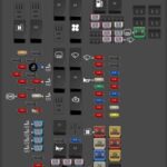
 2007 Ford F-150 passenger compartment fuse panel diagram illustrating the power distribution box location
This diagram shows the layout of the fuses and relays within the passenger compartment fuse panel. Refer to the table below for a detailed list of each fuse and its corresponding function. Notably, for diagnosing OBD2 port issues, you’ll want to pay close attention to fuse #41, which is often related to the diagnostic connector power.
| Type | No. | Description |
|---|---|---|
| Fuse MINI 10A | 1 | Run/Accessory – Wipers, Instrument cluster, Audio for XL/STX |
| Fuse MINI 20A | 2 | Stop/Turn lamps, Brake on/off switch, Hazard flashers View problems with the tail light fuse… View problems with the brake light fuse… |
| Fuse MINI 7.5A | 3 | Power mirrors, Memory seats and pedals, Driver power seat |
| Fuse MINI 10A | 4 | DVD battery power, Power fold mirror |
| Fuse MINI 7.5A | 5 | Keep alive memory for Powertrain Control Module (PCM) and climate control module |
| Fuse MINI 15A | 6 | Parklamps, BSM, Instrument panel illumination |
| Fuse MINI 5A | 7 | Radio (start signal) |
| Fuse MINI 10A | 8 | Heated mirrors, Switch indicator |
| Fuse MINI 20A | 9 | Fuel pump relay, Fuel injectors, Intake manifold runner control [4.2L] View problems with the fuel pump fuse… |
| Fuse MINI 20A | 10 | Trailer tow back-up lamps relay (PCB1), Trailer tow parklamp relay (R201) |
| Fuse MINI 10A | 11 | A/C clutch, 4×4 solenoid View problems with the air conditioning fuse… |
| Fuse MINI 5A | 12 | PCM relay coil |
| Fuse MINI 10A | 13 | Climate control module power, Flasher relay |
| Fuse MINI 10A | 14 | Back-up lamp and Daytime Running Lamps (DRL) relay coil, A/C pressure switch, Redundant speed control switch, Heated PCV [5.4L], Trailer tow back-up lamps relay coil, ABS, Reverse park aid, EC mirror, Navigation radio (reverse input) View problems with the headlight fuse… |
| Fuse MINI 5A | 15 | Overdrive cancel, Cluster, Traction control switch |
| Fuse MINI 10A | 16 | Brake-shift interlock solenoid |
| Fuse MINI 15A | 17 | Fog lamp relay (R202) |
| Fuse MINI 10A | 18 | Run/Start feed – Overhead power point, Electrochromatic mirror, Heated seats, BSM, Compass, RSS (Reverse Sensing System) |
| Fuse MINI 10A | 19 | Restraints (Air bag module), OCS |
| Fuse MINI 10A | 20 | Battery feed for overhead power point |
| Fuse MINI 15A | 21 | Cluster keep alive power |
| Fuse MINI 10A | 22 | Delayed accessory power for audio, power door lock switch and moon roof switch illumination |
| Fuse MINI 10A | 23 | RH low beam headlamp View problems with the headlight fuse… |
| Fuse MINI 15A | 24 | Battery saver power for demand lamps |
| Fuse MINI 10A | 25 | LH low beam headlamp View problems with the headlight fuse… |
| Fuse MINI 20A | 26 | Horn relay (PCB3), Horn power View problems with the horn fuse… |
| Fuse MINI 5A | 27 | Passenger Air bag Deactivation (PAD) warning lamp, Cluster RUN /START power |
| Fuse MINI 5A | 28 | SecuriLock transceiver (PATS), PCM IGN monitor |
| Fuse MINI 15A | 29 | PCM 4×4 power |
| Fuse MINI 15A | 30 | PCM 4×4 power |
| Fuse MINI 20A | 31 | Radio power, Satellite radio module View problems with the radio fuse… |
| Fuse MINI 15A | 32 | Vapor Management Valve (VMV), A/C clutch relay, Canister vent, Heated Exhaust Gas Oxygen (HEGO) sensors #11 and #21, CMCV, Mass Air Flow (MAF) sensor, VCT, Heated Positive Crankcase Ventilation (PCV) valve [4.2L engine], CID sensor [4.2L engine, 4.6L/4.2L EGR] , Electronic fan clutch [4.6L/5.4L engines] View problems with the air conditioning fuse… |
| Fuse MINI 15A | 33 | Shift solenoid, CMS #12 and #22, Ignition coils |
| Fuse MINI 15A | 34 | PCM power |
| Fuse MINI 20A | 35 | Instrument cluster high beam indicator, High beam headlamps View problems with the headlight fuse… |
| Fuse MINI 10A | 36 | Trailer tow right turn/stop lamps View problems with the tail light fuse… |
| Fuse MINI 20A | 37 | Rear power point, Center console power point |
| Fuse MINI 25A | 38 | Subwoofer power |
| Fuse MINI 20A | 39 | Instrument panel power point |
| Fuse MINI 20A | 40 | Low beam headlamps, DRL View problems with the headlight fuse… |
| Fuse MINI 20A | 41 | Cigar lighter, Diagnostic connector power View problems with the cigarette lighter fuse… |
| Fuse MINI 10A | 42 | Trailer tow left turn/stop lamps View problems with the tail light fuse… |
| Fuse FMX/JCase 30A | 101 | Starter solenoid |
| Fuse FMX/JCase 20A | 102 | Ignition switch feed |
| Fuse FMX/JCase 20A | 103 | ABS valves |
| Fuse FMX/JCase 30A | 105 | Electric trailer brakes |
| Fuse FMX/JCase 30A | 106 | Trailer tow battery charge |
| Fuse FMX/JCase 30A | 107 | Power door locks (BSM) |
| Fuse FMX/JCase 30A | 108 | Passenger power seat |
| Fuse FMX/JCase 30A | 109 | Driver power seat, Adjustable pedals, Memory module (pedals, seat, mirror) |
| Fuse FMX/JCase 30A | 111 | 4×4 relays |
| Fuse FMX/JCase 40A | 112 | ABS pump power |
| Fuse FMX/JCase 30A | 113 | Wipers and washer pump |
| Fuse FMX/JCase 40A | 114 | Heated backlite, Heated mirror power |
| Fuse FMX/JCase 20A | 115 | Not used (Spare) |
| Fuse FMX/JCase 30A | 116 | Blower motor |
| Fuse FMX/JCase 30A | 118 | Heated seats |
| Circuit breaker MAXI | 401 | Delayed accessory power: Power windows, Moon roof, Power sliding backlite (circuit breaker) |
| Relay | R01 | Starter solenoid |
| Relay | R02 | Accessory delay |
| Relay | R03 | Hi-beam headlamps |
| Relay | R04 | Heated backlite |
| Relay | R05 | Trailer tow battery charge |
| Relay | R06 | Blower motor |
| Relay | R201 | Trailer tow park lamps |
| Relay | R202 | Fog lamps |
| Relay | R203 | PCM |
Auxiliary Relay Box (with DRL) Diagram
For 2007 Ford F-150 models that include Daytime Running Lights (DRL), the auxiliary relay box in the engine compartment follows this configuration:
 2007 Ford F-150 auxiliary relay box diagram for models with daytime running lights
This diagram outlines the relays and fuses specific to models equipped with DRL. The table below details the function of each component within this auxiliary box.
| Type | No. | Description |
|---|---|---|
| Fuse ATO 5A | F03 | Clockspring illumination |
| Relay | R01 | 4×4 CCW |
| Relay | R02 | 4×4 CW |
| Relay | R03 | Daytime Running Lamps (DRL) high beam disable |
| Relay | R201 | (DRL) Daytime running lights |
| Relay | R202 | (A/C clutch) A/C magnetic clutch View problems with the air conditioning relay… |
| Diode ATO | D01 | (A/C clutch) A/C magnetic clutch |
Auxiliary Relay Box (without DRL) Diagram
If your 2007 Ford F-150 does not have Daytime Running Lights, the auxiliary relay box in the engine compartment will adhere to this diagram:
 2007 Ford F-150 auxiliary relay box diagram for models without daytime running lights
This diagram illustrates the setup for models without DRL. The table below provides a breakdown of the fuses, relays, and diodes within this auxiliary relay box.
| Type | No. | Description |
|---|---|---|
| Fuse ATO 5A | F03 | Clockspring illumination |
| Diode ATO | D01 | A/C clutch |
| Relay | R202 | A/C clutch View problems with the air conditioning relay… |
Finding the OBD2 Fuse for Diagnostics
When diagnosing your 2007 Ford F-150 with an OBD2 scanner, ensuring the OBD2 port has power is essential. The fuse that powers your OBD2 diagnostic port in the 2007 Ford F-150 is located in the passenger compartment fuse panel.
Referring back to the passenger compartment fuse panel diagram and table, fuse #41, a 20A Mini fuse, is designated for “Cigar lighter, Diagnostic connector power.” This fuse is the primary suspect if your OBD2 scanner is not powering up or connecting to your vehicle.
If you are experiencing issues connecting your OBD2 scanner to your 2007 Ford F-150, follow these steps:
- Locate the passenger compartment fuse panel. Consult your owner’s manual for the precise location, but it is often under the dashboard on the driver’s side.
- Identify fuse #41 (20A). Use the diagram and table provided to pinpoint the correct fuse.
- Check the fuse. Visually inspect the fuse for a broken filament. You can also use a fuse tester for a more definitive check.
- Replace if necessary. If the fuse is blown, replace it with a new 20A Mini fuse.
- Test your OBD2 scanner again. After replacing the fuse, try connecting your OBD2 scanner to see if it now powers on and communicates with your vehicle’s computer.
By understanding the fuse box layout and specifically identifying the OBD2 fuse, you can efficiently troubleshoot and resolve common diagnostic communication issues in your 2007 Ford F-150. Remember to always consult your vehicle’s owner’s manual for the most accurate and model-specific information.