For automotive enthusiasts and DIYers, having the right diagnostic tools is essential. While standard OBD2 ports have 16 pins, some specific applications, or custom setups might only require a streamlined 4 Pin Obd2 Connector. This guide provides a practical, step-by-step approach to creating your own 4-pin OBD2 connector harness. Please be aware, this is a DIY project and should be undertaken at your own risk. Incorrect wiring can potentially damage your vehicle’s electronic control unit (ECU).
Tools and Parts You’ll Need
Before you begin, gather the necessary tools and parts. This will ensure a smooth and efficient build process.
- Wire strippers/cutters
- Needle-nose pliers
- Molex crimping tool (optional, but recommended for professional crimps)
- Soldering iron and solder (recommended for enhanced connection strength)
- 4-Pin Connector (Suitable for 22-16AWG wire, insulation size 1.3-1.7mm)
- OBD-II Cable (Ensure it has the necessary wires)
For cost savings, if you have spare automotive wire, you can purchase a female OBD-II connector separately and wire it directly to the 4-pin connector, using appropriately sized wires. It’s crucial to match the wire size to the 4-pin connector pins for a secure and reliable connection.
Identifying the Essential Wires on the OBD-II Connector
A standard OBD-II connector (OBD2C) has 16 pins, but for this 4-pin setup, we will only utilize four critical connections. These are typically sufficient for basic diagnostic functions, particularly CAN bus communication which is common in modern vehicles.
The four pins we need from the OBD-II connector are:
- Pin 4: Chassis Ground (often an orange wire in the OBD2C cable)
- Pin 6: CAN High (CAN [J-2234] High, often a green wire in the OBD2C cable)
- Pin 14: CAN Low (CAN [J-2234] Low, often a brown wire with a white stripe in the OBD2C cable)
- Pin 16: Battery Power (often a green wire with a white stripe in the OBD2C cable)
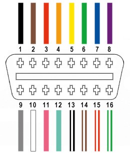 Wiring diagram highlighting the 4 pins of an OBD2 connector used for a custom 4-pin setup.
Step-by-Step Assembly Guide
Let’s walk through the process of assembling your 4 pin OBD2 connector.
Step 1: Prepare the OBD-II Cable Wires
Start by preparing the OBD-II cable. Many guides recommend twisting pairs of wires for signal integrity, especially for CAN bus systems. Begin by carefully removing the outer sheath and shielding from the OBD2C to expose the internal wires. Identify and separate the four wires you’ll be using (Pins 4, 6, 14, and 16 as listed above). Bundle the remaining 12 wires and secure them out of the way using a zip tie to keep your workspace tidy.
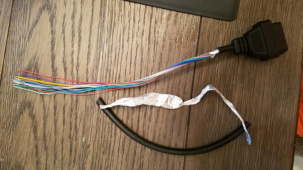 OBD2 cable with sheath and shielding removed to access internal wires for modification.
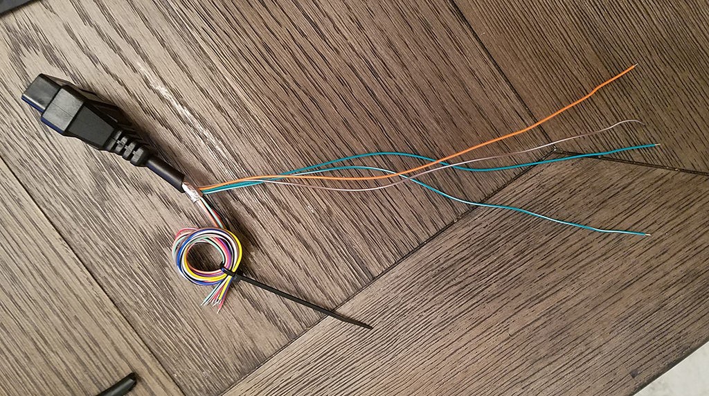 Four essential wires isolated from an OBD2 cable for creating a 4-pin diagnostic connector.
Step 2: Prepare Wire Ends and Seals for the 4-Pin Connector
A common issue when using pre-made OBD-II cables is that the internal wires are often 26AWG, which is thinner than the 22AWG pin size of many 4-pin connectors (4PC). To compensate for this difference in wire gauge, carefully strip about 3/8″ of insulation from the end of each of the four selected wires. Fold the exposed wire strands back over themselves and twist them tightly to effectively thicken the wire. This will ensure a better fit and contact within the 4-pin connector pins. Slide a rubber seal (provided with the 4PC kit) onto each wire. These seals are crucial for environmental protection, keeping out moisture and debris.
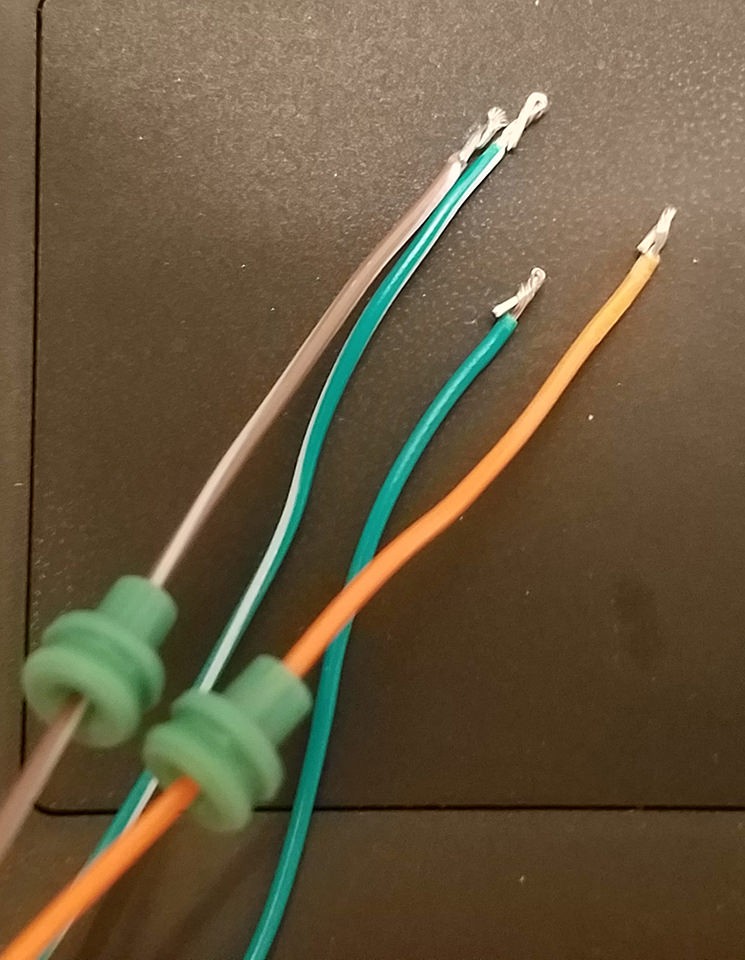 Rubber seals slid onto the prepared wires before crimping to ensure environmental protection for the connector.
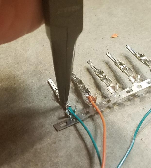
Step 3: Attaching Pins to Wires
Examine the pins for the 4PC. Each pin has two sets of prongs. The front prongs are designed to crimp onto the exposed wire, while the rear prongs crimp onto the wire insulation/seal. Insert the prepared wire into the front section of the pin, ensuring the exposed wire aligns with the front set of prongs. Due to the thin gauge of the OBD-II cable wires, you might find it helpful to use needle-nose pliers to hold the wire in place during the next steps.
 Close-up showing wire thickness relative to the pin connector, emphasizing the need to thicken thinner wires for secure connection.
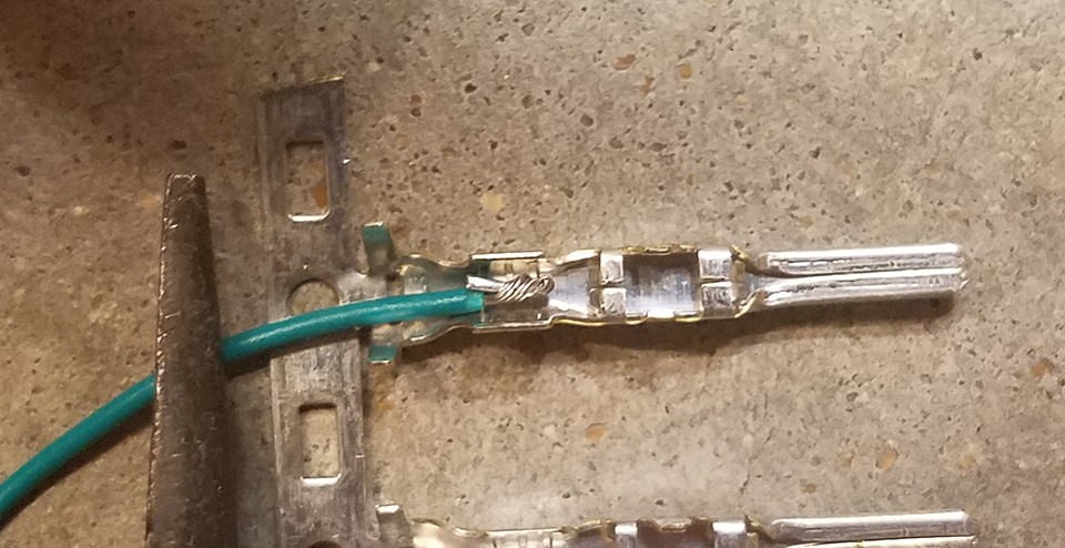
Step 4: Soldering (Recommended) or Crimping the Wire to the Pin
For a robust and reliable connection, soldering is highly recommended. Solder the wire to the pin connector. Soldering provides a solid electrical and mechanical bond, which is particularly beneficial when working with fine wires. If you choose to solder, ensure you have a clean solder joint. If you prefer crimping, and have a Molex crimping tool, proceed to step 5.
 Soldering the wire to the pin connector for a robust electrical and mechanical connection.
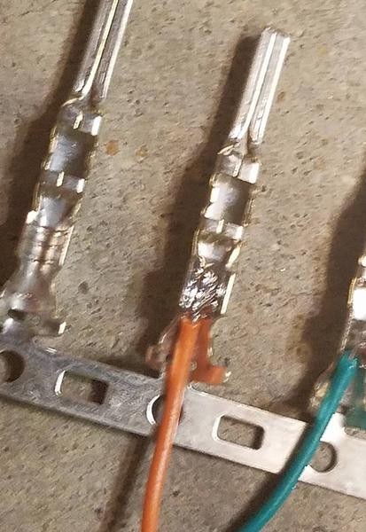
Step 5: Crimping the Front Prongs (If Not Soldering)
If you are crimping instead of soldering, use a Molex crimping tool for the best results. If you don’t have one, needle-nose pliers can be used. Carefully fold one of the front prongs over the wire using the pliers, then repeat for the other prong. For additional security, you can gently squeeze the prongs further down with the pliers, but be careful not to damage the pin.
 Using needle-nose pliers to crimp the pin connector prongs over the wire, securing it in place without a dedicated crimping tool.
 A completed crimped pin connector showing the wire securely fastened after using pliers.
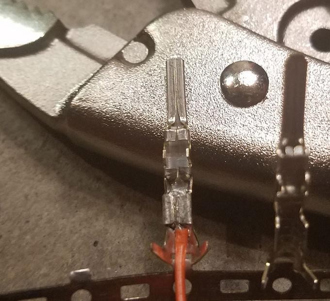
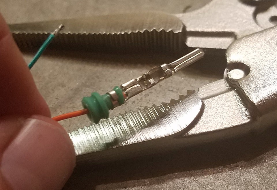
Step 6: Crimping the Rear Prongs Over the Seal
Slide the rubber seal up the wire until it sits between the rear set of prongs on the pin. Use the same crimping technique as before to fold these prongs over the rubber seal. This secures the seal and provides strain relief for the wire.
 Positioning the rubber seal to fit snugly against the back prongs of the pin connector for environmental sealing.
 Folding the back prongs of the pin connector over the rubber seal to finalize the secure and sealed connection.
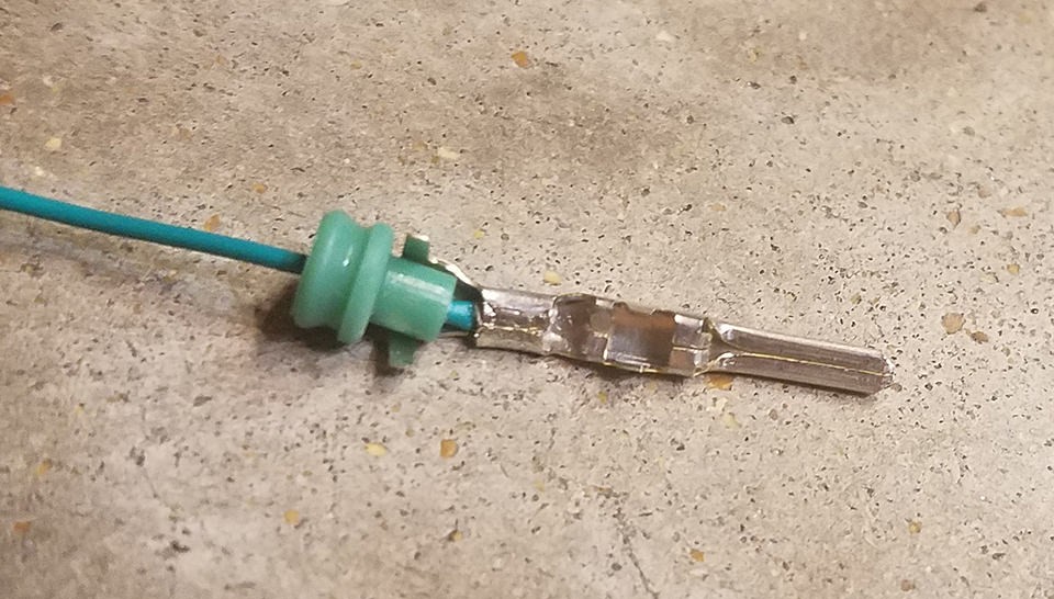
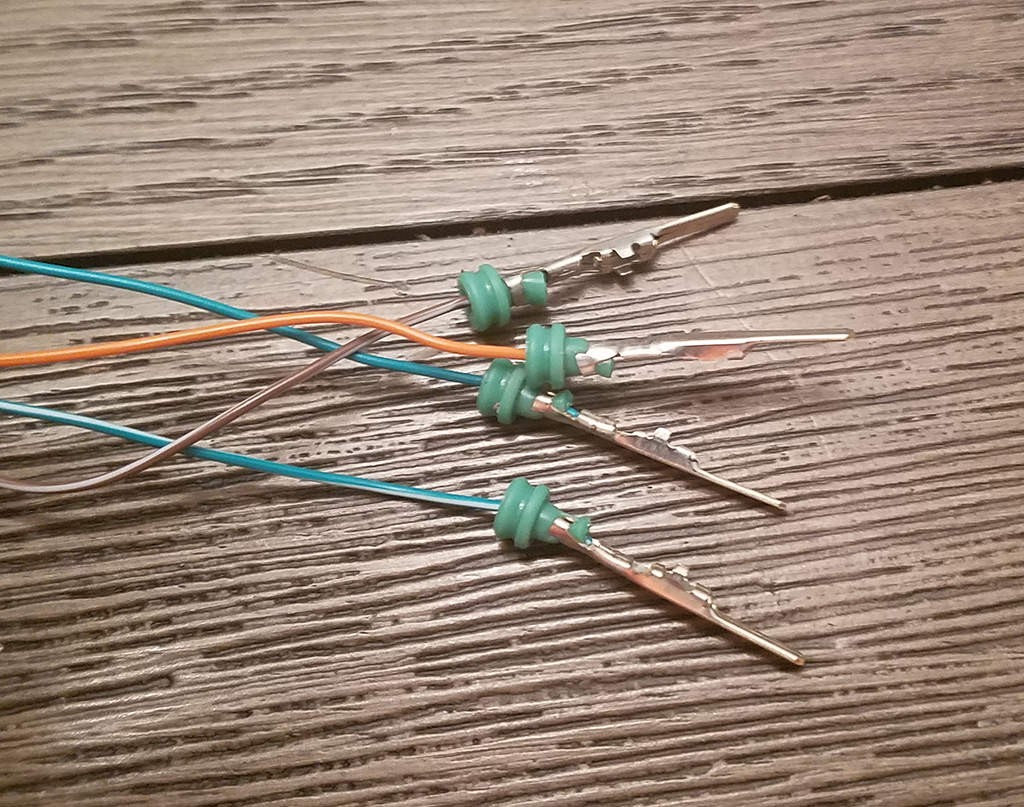 Finished pin connector with crimped prongs and seal, ready for insertion into the 4-pin housing.
Step 7: Wire Pairing and Twisting (Recommended)
While not always strictly necessary for basic diagnostic tasks, twisting wire pairs is a good practice, especially for CAN bus communication. It helps reduce electromagnetic interference. Pair and twist the wires as follows:
- Pin 4 (orange) with Pin 16 (green w/white stripe)
- Pin 6 (green) with Pin 14 (brown w/white stripe)
Step 8: Inserting Pins into the 4-Pin Connector Housing
Refer to the 4-pin connector diagram to ensure correct pin placement. Insert the pins into the 4PC housing from the rear in the following orientation:
- Pin 14 (brown w/white stripe) -> Connector Slot A
- Pin 6 (green) -> Connector Slot B
- Pin 16 (green w/white stripe) -> Connector Slot C
- Pin 4 (orange) -> Connector Slot D
Push each pin in until you hear a distinct “click,” indicating it is locked securely in place. Using needle-nose pliers to gently pull the wire from the rear can help ensure the pin is fully seated and locked.
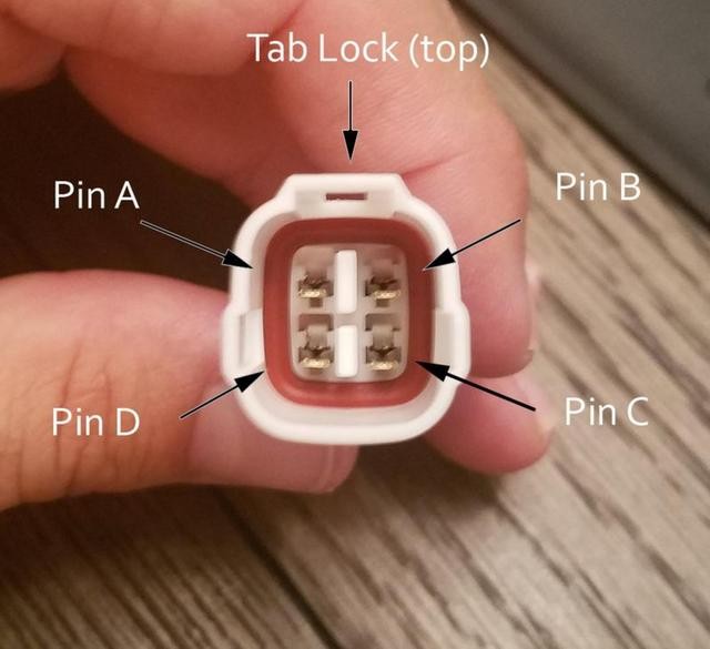 Diagram illustrating the correct pin insertion order into the 4-pin connector housing (A, B, C, D) with corresponding wire colors.
Completion and Testing
Congratulations! Your 4 pin OBD2 connector is now complete.
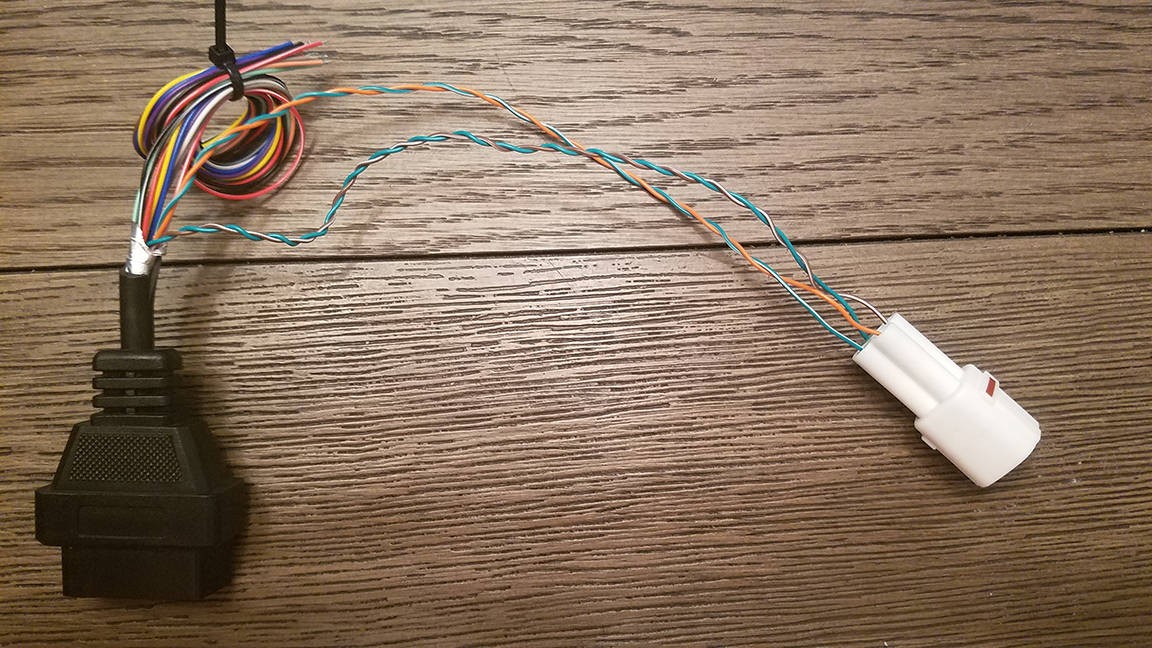 Assembled 4-pin OBD2 connector, showcasing the final product of the DIY wiring project.
 Hand holding the custom-made 4-pin OBD2 connector, demonstrating its compact size and usability.
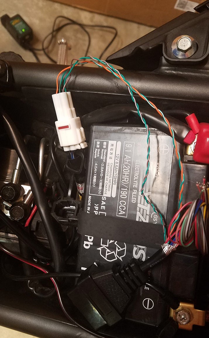
Before using it for critical diagnostics, it’s advisable to test your new connector. You can use it to check for and clear non-critical error codes on your vehicle to verify its functionality.
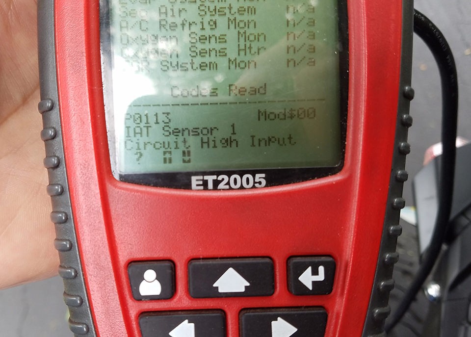 Testing the newly created 4-pin OBD2 connector to verify functionality and error code clearance.
By following these steps, you can create a functional 4 pin OBD2 connector for your specific diagnostic needs. Remember to always double-check your wiring and exercise caution when working with vehicle electronics.