So, you’re looking to dive into the world of DIY car diagnostics? Fantastic! One of the first hurdles you might encounter is connecting your car’s OBD2 port to your computer. While there are commercial OBD2 to USB cables available, building your own can be a rewarding and cost-effective project. This guide will walk you through creating a simple Diy Obd2 To Usb Wiring Diagram and building your own harness.
Disclaimer: Before we get started, it’s crucial to understand that working with car electronics carries risks. I am not a professional, and this guide is based on my personal experience. Follow these steps at your own risk. I’m not responsible for any damage to your vehicle, ECU, or any unforeseen consequences. If you’re uncomfortable with DIY electronics, it’s always best to consult a professional.
Tools & Parts You’ll Need
To get started, gather these tools and parts:
Tools:
- Wire strippers/cutters: Essential for preparing the wires.
- Needle-nose pliers: Helpful for handling small components and crimping.
- Molex crimping tool (Optional but Recommended): For professional-looking and secure crimps.
- Soldering iron (Recommended): To create a more robust and reliable connection.
Parts:
- 4-Pin Connector: This connector will interface with your OBD2 cable. You can find suitable connectors at electronic component suppliers. Ensure it’s compatible with 22-16AWG wire and has an insulation/seal size of 1.3-1.7mm. (Example Connector)
- OBD-II Cable: You’ll need an OBD-II cable to salvage the necessary connector and wires. (Example OBD-II Cable)
If you have spare wires on hand, you can purchase just the female OBD-II connector and wire, potentially saving some cost. However, ensure you know the gauge of your spare wire to select the correct 4-pin connector.
Understanding the OBD2 Connector Wiring
The OBD2 connector (often referred to as OBD2C) has 16 pins, but for our basic USB connection, we only need four:
- Pin 4 (Chassis Ground): Typically an orange wire on the OBD2 cable. This provides the ground connection.
- Pin 6 (CAN High – J-2284): Usually a green wire. This is part of the CAN bus communication network for diagnostics.
- Pin 14 (CAN Low – J-2284): Often a brown wire with a white stripe. The other part of the CAN bus communication network.
- Pin 16 (Battery Power): Typically a green wire with a white stripe. Provides power to the OBD2 interface.
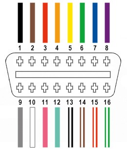 OBD2 Connector Pinout
Step-by-Step Wiring Guide
Let’s get our hands dirty and start building this diy obd2 to usb wiring diagram in real life!
Step 1: Prepare the OBD2 Cable Wires
Based on common practice for data transmission, it’s recommended to twist pairs of wires to reduce interference. Start by carefully removing the outer sheath and shielding from the OBD2 cable. Separate the four wires we identified earlier (pins 4, 6, 14, and 16). Bundle the remaining 12 wires together and secure them with a zip tie to keep them out of your way.
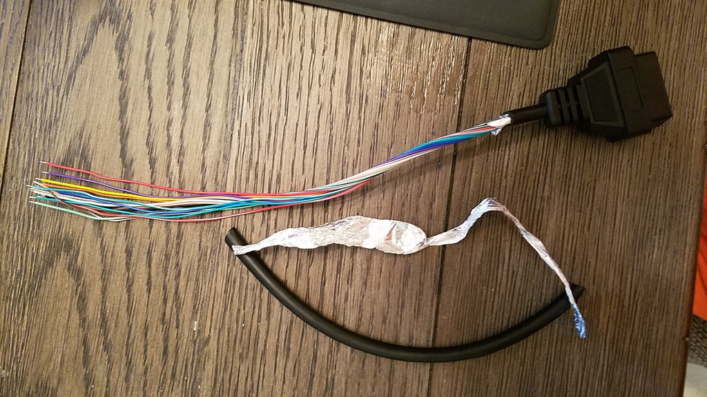 Stripped OBD2 Cable Sheath
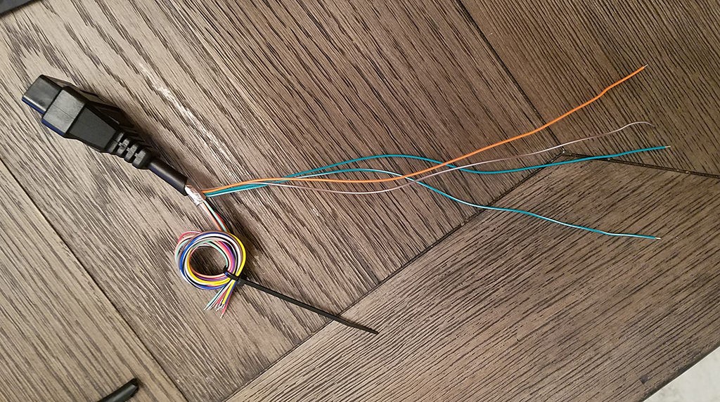 Separated OBD2 Wires
Step 2: Prepare the Wires for the 4-Pin Connector
The wires in the OBD2 cable are often 26AWG, which is smaller than the 22AWG size that the pins of our 4-pin connector (4PC) are designed for. To compensate, we need to “thicken” the wire.
The OBD2 cable wires usually come pre-stripped with about 1/8″ of exposed wire. Strip off more insulation until approximately 3/8″ of wire is exposed. Fold the exposed wire back onto itself, twisting it to increase its thickness. This will ensure a better fit within the 4-pin connector pins.
Slide one of the rubber seals (included with the 4PC kit) onto each of the four prepared wires.
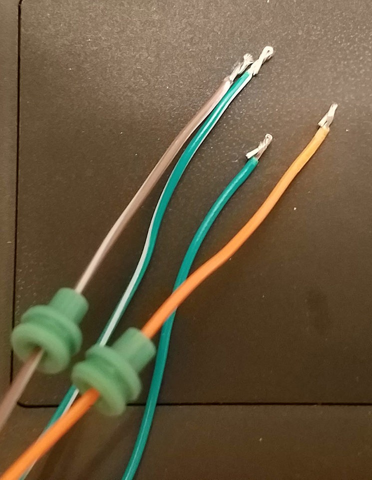 Preparing Wires and Seals
Step 3: Attach Wires to 4-Pin Connector Pins
The pins for the 4-pin connector have two sets of prongs. One set is designed to crimp onto the exposed wire, and the other set crimps onto the rubber seal. Insert the prepared wire into the pin, aligning it with the front set of prongs.
 Wire and Connector Pin Comparison
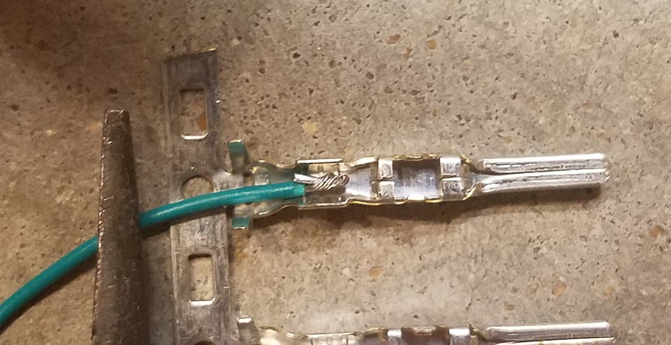
Step 4: Soldering the Wires (Recommended)
Soldering provides a strong and electrically sound connection, especially beneficial when working with smaller gauge wires like these. Solder the wire to the pin connector. If your soldering skills are a bit rusty, there are many helpful tutorials online, like this YouTube video which offers soldering tips.
 Soldering Wire to Pin Connector
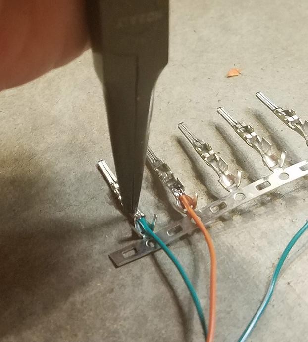
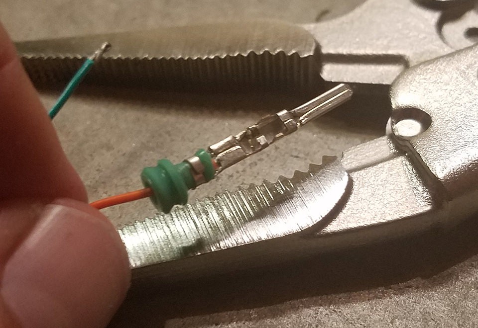
Step 5: Crimping the Connector Pins (Alternative to Soldering)
If you have a Molex crimping tool, this is the ideal method for securing the wire to the pin. If not, needle-nose pliers can be used as an alternative.
Using needle-nose pliers at an angle, carefully begin to fold one set of prongs over the exposed wire. Repeat for the other prong, ensuring a tight crimp. This YouTube video provides guidance on crimping techniques without a specialized tool. For extra security, you can gently crush the prongs further with pliers, though be careful not to damage the connector.
 Crimping Connector Prongs – Step 1
 Crimped Connector Prongs – Wire
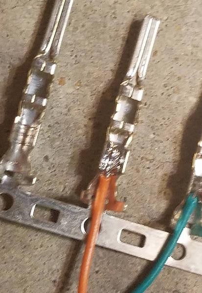
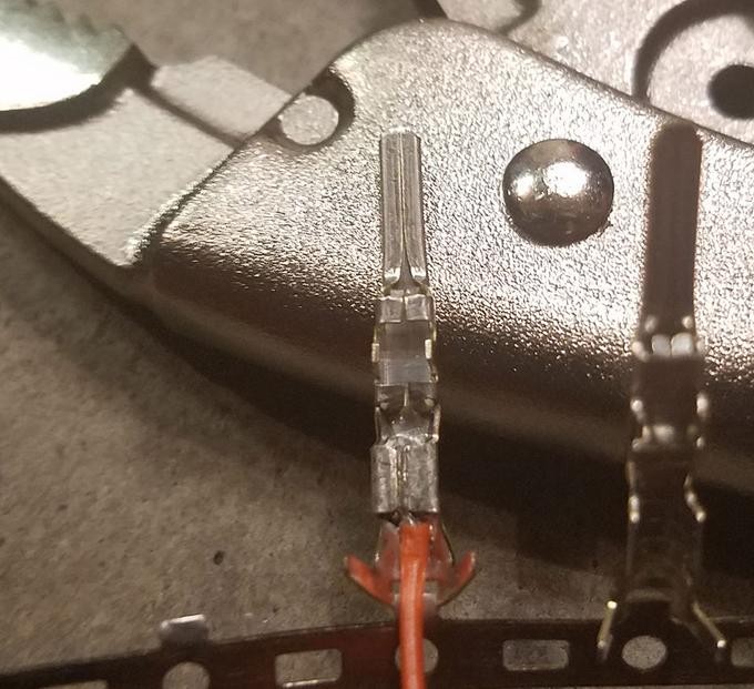
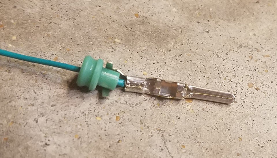
Step 6: Crimping the Seal Prongs
Slide the rubber seal up the wire until it sits between the second set of prongs on the connector pin. Use the same crimping technique as before to fold these prongs over the rubber seal. This secures the seal and provides strain relief and environmental protection.
 Crimping Seal Prongs – Step 1
 Crimping Seal Prongs – Step 2
 Crimped Seal Prongs – Final
Step 7: Wire Pairing and Twisting
While not definitively proven to be necessary, many DIY guides recommend pairing and twisting specific wires. Pair and twist the wires as follows:
- Pin 4 (Orange) / Pin 16 (Green w/white stripe)
- Pin 6 (Green) / Pin 14 (Brown w/white stripe)
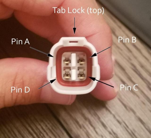
Step 8: Insert Pins into the 4-Pin Connector Housing
Now, insert the pins into the 4-pin connector housing (4PC) in the correct orientation as shown below:
- Pin 14 (Brown w/white stripe): Connector slot A
- Pin 6 (Green): Connector slot B
- Pin 16 (Green w/white stripe): Connector slot C
- Pin 4 (Orange): Connector slot D
Insert each pin from the rear of the connector housing until you hear a click, indicating it’s locked in place. Needle-nose pliers can help gently pull the wire to ensure it’s securely seated.
 4-Pin Connector Pin Insertion
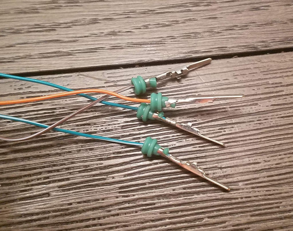
Completion and Testing
Congratulations! You’ve completed your diy obd2 to usb wiring diagram and built your own OBD2 to 4-pin harness.
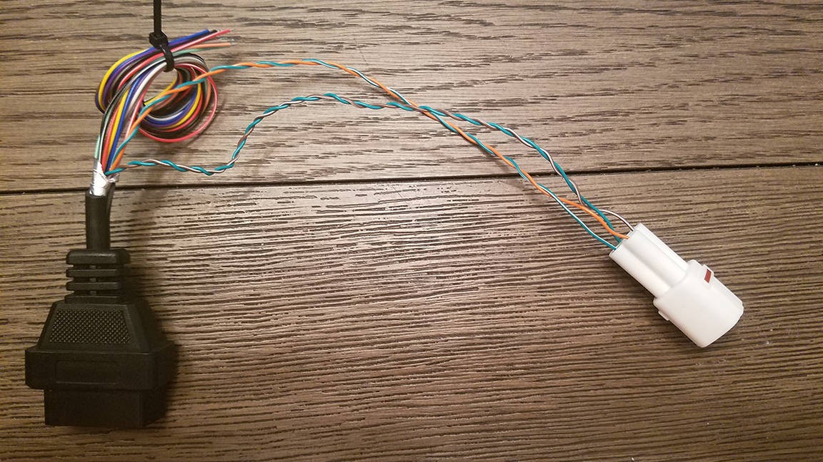 Completed Wiring Harness
 Close-up of Completed Harness
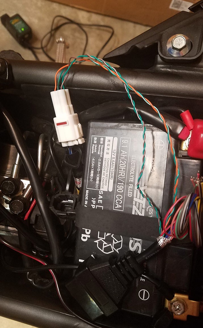
Now, you can use this harness with a suitable USB adapter (not covered in this guide) to connect your OBD2 port to your computer for diagnostic purposes.
The harness was successfully tested to read and clear a fault code.
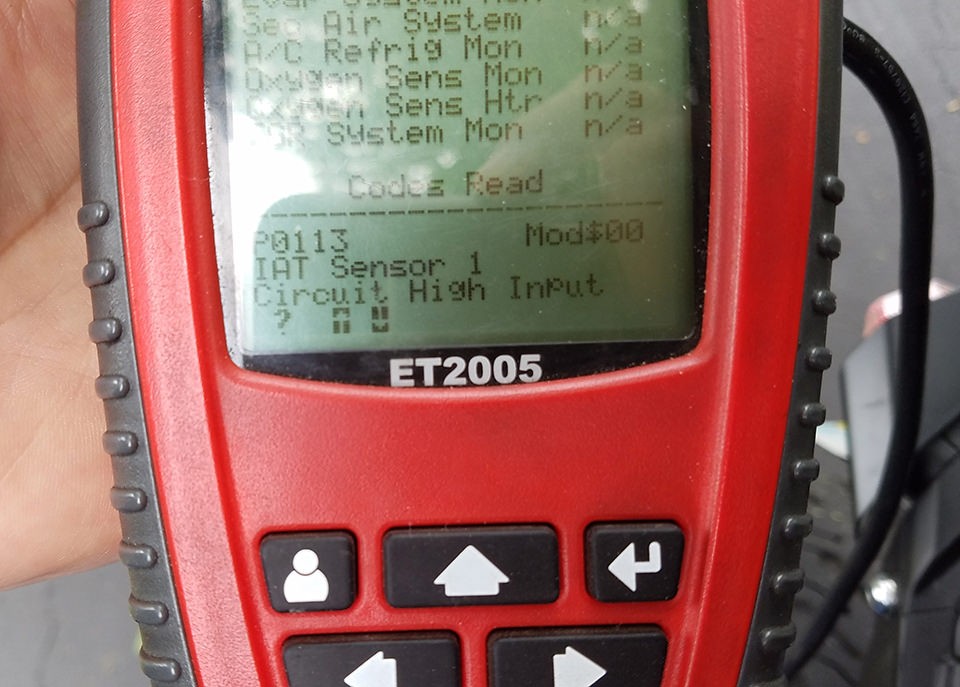 Successful Error Clearing
If any step is unclear or you require further clarification, feel free to ask for more detailed explanations or additional photos. Happy diagnosing!