Fuses are essential components in your 2000 Ford Ranger’s electrical system. They act as safety devices, protecting various circuits from overloads that can damage components or even cause fires. If you’re experiencing electrical issues in your Ranger, such as malfunctioning lights, power windows, or accessories, a blown fuse is often the culprit. Before you start replacing expensive parts, checking your fuse boxes is the first and easiest step in diagnosing the problem.
This guide will walk you through locating the fuse boxes in your 2000 Ford Ranger, understanding the fuse diagrams, and how to check and replace fuses effectively. Knowing your fuse box layout is crucial for any Ford Ranger owner for basic troubleshooting and maintenance.
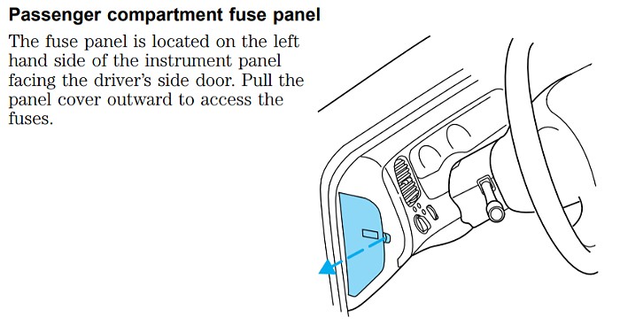
Passenger Compartment Fuse Panel
The primary fuse panel in your 2000 Ford Ranger is located inside the cabin, making it easily accessible for quick checks.
Location: You’ll find the passenger compartment fuse panel on the left end of the instrument panel, essentially on the driver’s side dashboard. To access it, you’ll need to locate a small indentation or divot on the fuse panel cover. Gently insert your finger into this divot and pull the cover towards you to remove it.
Once you remove the cover, you’ll expose the fuse panel and a handy diagram on the underside of the cover. This diagram is your key to identifying which fuse controls which circuit. The cover also conveniently holds spare fuses for common amperage ratings, and a fuse pulling tool to simplify fuse removal.
 Passenger Compartment Fuse Panel Location in a Ford Ranger
Passenger compartment fuse panel location on a Ford Ranger dashboard, highlighting driver’s side access.
Below is the diagram specific to the 1998-2000 Ford Ranger passenger compartment fuse box. Refer to this chart to understand the function of each fuse in your panel.
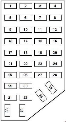 1998-2000 Ford Ranger Passenger Compartment Fuse Box Diagram
Fuse diagram for the passenger compartment fuse box of a 1998-2000 Ford Ranger, detailing fuse number, amperage, and protected circuits.
| No. | AMPS | Circuits protected |
|---|---|---|
| 1 | 7.5 | Power Mirror Switch |
| 2 | 7.5 | Blower Motor Relay, PAD Module, Air Bag Diagnostic Monitor |
| 3 | 7.5 | Left Stop/Turn Trailer Tow Connector |
| 4 | 10 | Left Headlamp |
| 5 | 10 | 1998-1999: Data Link Connector (DLC) |
| 6 | 15 | 2000: Overdrive, Back-up Lamps, DRL, 4×4 |
| 7 | 7.5 | Right Stop/Turn Trailer Tow Connector |
| 8 | 10 | Right Headlamp, Fog Lamp Relay |
| 9 | 7.5 | Brake Pedal Position Switch |
| 10 | 7.5 | Speed Control Servo/Amplifier Assembly, Generic Electronic Module (GEM), Shift Lock Actuator, Blend Door Actuator, A/C-Heater Assembly, Turn Signals |
| 11 | 7.5 | Instrument Cluster, Daytime Running Lights (DRL), RABS Resistor |
| 12 | — | Not Used |
| 13 | 20 | Brake Pedal Position Switch |
| 14 | 20 | Rear Anti-Lock Brake System (RABS) Module |
| 10 | 4 Wheel Anti-Lock Brake System (4WABS) Module, 4WABS Main Relay | |
| 15 | 7.5 | Air Bag Indicator Lamp, Alternator Indicator Lamp, Instrument Cluster |
| 16 | 30 | Windshield Wiper Motor, Wiper Hi-Lo Relay, Wiper Run/Park Relay |
| 17 | 25 | Cigar Lighter, Data Link Connector (DLC; 2000) |
| 18 | 15 | Driver’s Unlock Relay, All-Unlock Relay, All-Lock Relay |
| 19 | 25 | PCM Power Diode, Ignition, PATS |
| 20 | 7.5 | RAP Module, Generic Electronic Module (GEM), Radio |
| 21 | 15 | Flasher (Hazard) |
| 22 | 20 | Auxiliary Power Socket |
| 23 | — | Not Used |
| 24 | 7.5 | Clutch Pedal Position (CPP) switch, Starter Interrupt Relay, Anti-Theft |
| 25 | 7.5 | 1998-1999: Generic Electronic Module (GEM), Instrument Cluster |
| 26 | 10 | Battery Saver Relay, Electronic Shift Relay, Interior Lamp Relay, Power Window Relay, Electronic Shift Control Module, Dome/Map Lamp, GEM, Instrument Cluster (2000) |
| 27 | 15 | 1998-1999: Electric Shift, Backup Lamps, Daytime Running Lamps (DRL), Transmission Control Switch, Pulse Vacuum Hub Lock |
| 28 | 7.5 | Generic Electronic Module (GEM), Radio |
| 29 | 15 | Radio |
| 30 | 10 | 1999-2000: RABS Test Connector |
| 15 | 1998: Park Lamp/Trailer Tow Relay | |
| 31 | — | Not Used |
| 32 | — | Not Used |
| 33 | 15 | Headlamps, Daytime Running Lamps (DRL) Module, Instrument Cluster |
| 34 | — | Not Used |
| 35 | 15 | 1999: Park Lamp/Trailer Tow Relay |
| 10 | 1998: RABS Test Connector | |
| 36 | — | Not Used |
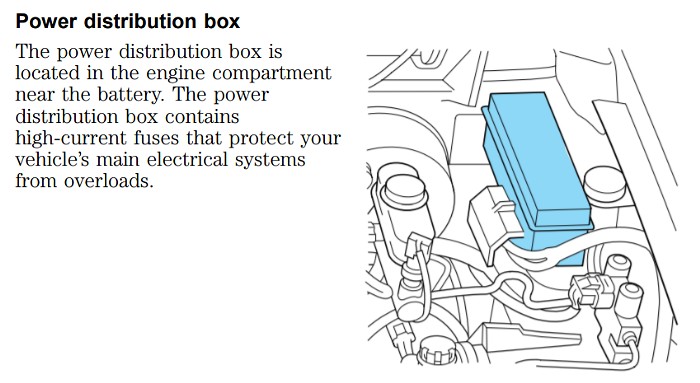
Power Distribution Box (Engine Bay Fuse Box)
In addition to the passenger compartment fuse panel, your 2000 Ford Ranger also has a power distribution box, often referred to as the engine bay fuse box. This box houses fuses and relays that manage higher-current systems.
Location: The power distribution box is situated in the engine compartment on the driver’s side. Look for it near the fender, mounted on a bracket attached to the fender apron. It’s usually a black plastic box, clearly identifiable as a fuse and relay housing.
 Ford Ranger Power Distribution Box Location in Engine Bay
Location of the power distribution box within the engine bay of a Ford Ranger, positioned on the driver’s side near the fender.
The following diagram details the fuses and relays within the power distribution box of your 2000 Ford Ranger.
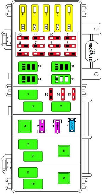 1998-2000 Ford Ranger Engine Bay Fuse Box Diagram
Detailed fuse and relay diagram for the engine bay power distribution box in 1998-2000 Ford Ranger models.
| No. | AMPS | Circuits protected |
|---|---|---|
| 1 | 50 | I/P Fuse Panel |
| 2 | 40 | Blower Motor Relay |
| 3 | 50 | 4 Wheel Anti-Lock Brake System (4WABS) Module |
| 4 | 20 | Power Windows |
| 5 | 50 | Ignition Switch, Starter Relay |
| 1 | 10 | A/C Relay |
| 2 | 20 | Auxiliary Power Point |
| 3 | 20 | Electronic Shift Relay and Electronic Shift Control Module |
| 4 | 20 | 2000: Fog Lamp and Daytime Running Lamps |
| 15 | 1998-1999: Fog Lamp and Daytime Running Lamps | |
| 5 | 15 | 2000: Trailer Tow Park Lamps |
| 10 | 1998: Air Bag Diagnostic Monitor | |
| 6 | 10 | Powertrain Control Module |
| 7 | 30 | 4 Wheel Anti-lock Brake System (4WABS) Module |
| 8 | 30 | PCM Relay |
| 9 | 20 | Fuel Pump Relay and RAP Module |
| 10 | 15 | Horn Relay |
| 11 | 15 | Parklamps Relay and Main Light Switch |
| 12 | 30 | Mam Light Switch and Multifunction Switch |
| 13 | 15 | Heated Oxygen Sensor, EGR Vacuum Regulator, EVR Solenoid, Camshaft Position Sensor (CMP), Canister Vent Solenoid |
| 14 | 30 | Alternator Voltage Regulator |
| 15 | — | Not Used |
| 1 | Wiper Park Relay | |
| 2 | A/C Relay | |
| 3 | Wiper Hi/Lo Relay | |
| 4 | PCM Power Relay | |
| 5 | Fuel Pump Relay | |
| 6 | Starter Relay | |
| 7 | Horn Relay | |
| 8 | 1999-2000: Fog Lamp Control Relay 1998: Washer Pump Relay | |
| 9 | Blower Motor Relay | |
| 10 | 1999-2000: Foglamp Isolation Relay 1998: Foglamp Relay | |
| 11 | Not Used | |
| 12 | Not Used | |
| 13 | Park Lamp/Trailer Tow Relay | |
| 14 | Washer Pump Relay | |
| 1 | RABS Resistor | |
| 1 | RABS Diode | |
| 2 | Electronic Engine Controls Diode |
Step-by-Step Guide to Checking and Replacing Fuses
Once you’ve identified the fuse box and located the fuse you suspect is blown using the diagrams, follow these steps to check and replace it:
-
Access the Fuse Panel: For the passenger compartment fuse panel, remove the cover as described earlier. For the power distribution box, you’ll typically need to unclip or unlatch the cover to access the fuses and relays inside.
-
Locate the Fuse: Refer to the fuse panel cover diagram or the diagrams provided in this article to pinpoint the fuse number corresponding to the circuit you’re investigating.
-
Inspect the Fuse: Visually check the fuse. Most fuses are transparent, allowing you to see the internal wire. If the thin metal wire inside the fuse is broken or melted, the fuse is blown and needs replacement.
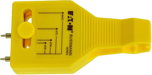
For a more definitive test, especially if visual inspection is unclear, you can use a fuse tester. These inexpensive tools, like the Bussmann fuse tester, allow you to test a fuse without removing it. Simply align the tester prongs with the metal test points on top of the fuse. If the indicator light illuminates, the fuse is good. If it doesn’t light up, the fuse is blown.
Bussmann fuse tester used to check a fuse without removal, showing the testing prongs and indicator light.
-
Replace the Fuse: If the fuse is blown, use the fuse pulling tool (usually found in the passenger compartment fuse box cover or your Ranger’s toolkit) to carefully remove the old fuse. Crucially, always replace a blown fuse with a new fuse of the exact same amperage rating. The amperage rating is printed on the fuse and is also indicated by its color.
WARNING: Using a fuse with a higher amperage rating than specified is extremely dangerous. It can bypass the circuit protection, leading to severe wire damage, overheating, and potentially a vehicle fire.
-
Reinstall the Cover: Once you’ve replaced the fuse, securely reattach the fuse panel cover or power distribution box cover.
-
Test the Circuit: After replacing the fuse, test the affected electrical component to see if it’s now working correctly. If the new fuse blows immediately or shortly after replacement, it indicates a persistent problem in the circuit that needs further diagnosis by a qualified mechanic.
 Bussmann Fuse Tester
Understanding Fuse Color Codes and Ratings
Fuses are color-coded to easily identify their amperage rating. This standardized color-coding system makes it simple to select the correct replacement fuse.
 Fuse Color and Amperage Ratings Chart
Chart displaying standard automotive fuse colors and their corresponding amperage ratings, aiding in correct fuse identification and replacement.
Refer to this color chart to ensure you are using the correct amperage fuse for each circuit in your 2000 Ford Ranger. Using the right fuse is vital for maintaining the electrical system’s safety and preventing damage.
By understanding the fuse box locations, diagrams, and fuse replacement procedures for your 2000 Ford Ranger, you can confidently tackle basic electrical troubleshooting and maintenance, saving time and money on simple repairs. Remember, if you are unsure or if fuses continue to blow, it’s always best to consult a professional automotive technician.