Ever found yourself needing to connect an OBD2 scanner to a vehicle with a different diagnostic port, specifically a 4-pin connector? This situation isn’t uncommon, especially with older vehicles or certain types of equipment. Instead of buying a potentially expensive adapter, you can easily make one yourself. This guide will walk you through creating a simple and effective 4-pin to OBD2 adapter cable, allowing you to read diagnostic information and troubleshoot your vehicle efficiently.
Disclaimer: This is a DIY guide for informational purposes. The author is not a professional mechanic. Follow these steps at your own risk. Incorrect wiring can potentially damage your vehicle’s ECU or other systems. If you are not comfortable with automotive wiring, consult a professional.
Tools and Parts You’ll Need
Before you begin, gather the necessary tools and parts. Having everything ready will make the process smoother and faster.
- Wire strippers/cutters: Essential for preparing the wires by removing insulation and cutting them to the desired length.
- Needle-nose pliers: Useful for handling small components, especially when crimping or inserting pins into connectors.
- Molex crimping tool (Optional but Recommended): While not strictly required, a crimping tool ensures a secure and professional connection between wires and connector pins.
- Soldering iron (Recommended): Soldering provides a robust and reliable electrical connection. It’s highly recommended for this project, though crimping can be used as an alternative.
- 4-pin connector: This connector will interface with the vehicle’s diagnostic port. Ensure it’s compatible with your vehicle’s 4-pin port. You can find a suitable connector here (pin/wire size = 22-16AWG; insulation/seal size = 1.3-1.7mm).
- OBD-II Cable: This cable has the standard OBD2 connector to plug into your scanner. A suitable OBD-II cable can be found here.
For cost savings, if you have spare automotive wire, you can purchase just the female OBD-II connector and wire the 4 necessary connections directly to the 4-pin connector. Ensure you choose the correct 4-pin connector and pins compatible with your wire gauge.
Understanding the Wiring: 4 Pin to OBD2
The OBD2 connector has 16 pins, but for this adapter, we only need to focus on four crucial connections. These pins carry the essential signals for basic diagnostic communication.
The OBD2 connector pins we will be using are:
- Pin 4: Chassis Ground (often an orange wire in the linked OBD2 cable) – Provides a common ground reference for the electrical circuit.
- Pin 6: CAN (J-2234) High (often a green wire in the linked OBD2 cable) – Carries the CAN High signal for data communication.
- Pin 14: CAN (J-2234) Low (often a brown wire with a white stripe in the linked OBD2 cable) – Carries the CAN Low signal for data communication.
- Pin 16: Battery Power (often a green wire with a white stripe in the linked OBD2 cable) – Provides power to the OBD2 scanner.
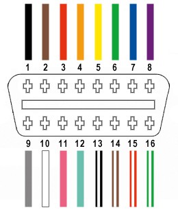 OBD2 Connector Pinout
Step-by-Step Guide to Building Your Adapter
Let’s get started on assembling your 4 Pin To Obd2 adapter cable. Follow these steps carefully to ensure proper wiring and functionality.
Step 1: Prepare the OBD2 Cable Wires
The OBD2 cable typically contains many wires, but we only need four. To keep things tidy, we’ll isolate and prepare only the necessary wires.
- Begin by carefully removing the outer sheath and shielding from the OBD2 cable to expose the individual wires inside.
- Identify the four wires corresponding to OBD2 pins 4, 6, 14, and 16 based on the color codes mentioned earlier (orange, green, brown/white, green/white – colors may vary, refer to your cable’s documentation if available or trace back from the OBD2 connector pins).
- Separate these four wires from the rest of the wires in the OBD2 cable.
- Bundle the remaining 12 unused wires together and secure them with a zip tie to keep them out of the way and prevent accidental shorts.
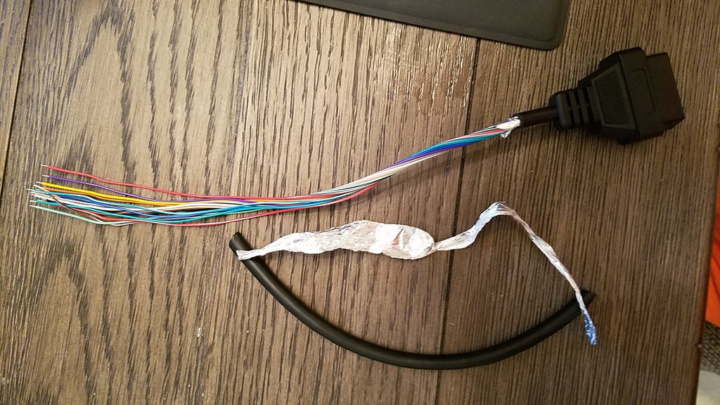 Stripped OBD2 Cable Sheath and Shielding
 Separated Wires for 4 Pin Connector
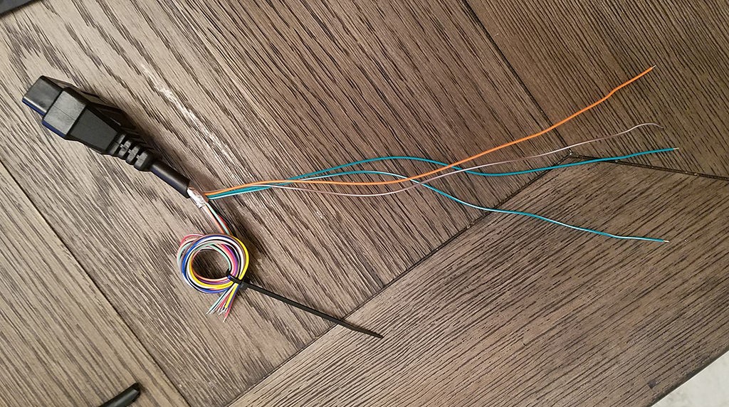
Step 2: Prepare the Wires for the 4-Pin Connector Pins
The wires in the OBD2 cable are often a smaller gauge (26AWG) than ideally suited for the pins of the 4-pin connector (designed for 22AWG). To ensure a good connection, we need to slightly thicken the wire ends.
- The OBD2 cable wires usually come pre-stripped with a short length of exposed wire (around 1/8 inch). Strip off a bit more insulation, aiming for about 3/8 inch of exposed wire.
- To increase the wire thickness, carefully fold the exposed wire strands over onto themselves.
- Twist the folded wire strands tightly together to create a thicker wire end that will fit more snugly into the 4-pin connector pins.
- Take one of the rubber seals included with the 4-pin connector kit and slide it onto each of the four prepared wires. These seals will provide environmental protection at the connector.
 Prepared Wire with Rubber Seal
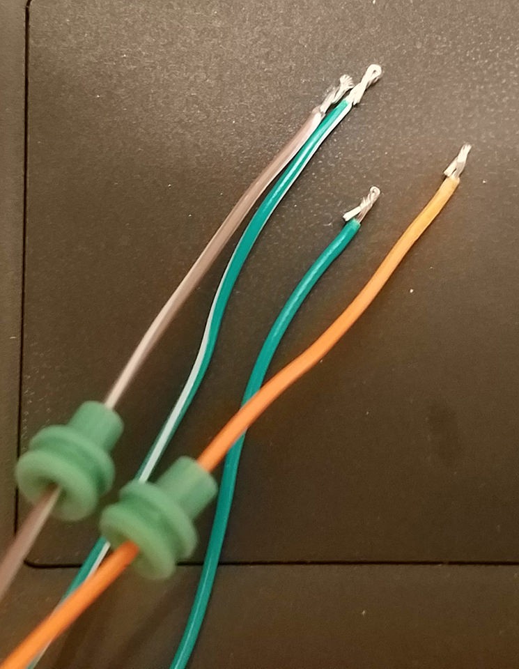
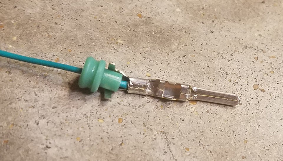
Step 3: Attach Wires to 4-Pin Connector Pins
Now it’s time to connect the prepared wires to the pins of the 4-pin connector. The pins have two sets of prongs: one for gripping the wire and another for gripping the rubber seal.
- Insert the exposed wire into the front part of a 4-pin connector pin, ensuring the wire sits between the first set of prongs (the ones closer to the pin tip).
- Notice how the wire gauge looks small compared to the pin. This highlights why thickening the wire in the previous step is important.
- Use needle-nose pliers to hold the wire in place during the next step, especially if you are soldering.
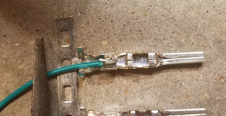 Wire Inserted into Connector Pin
Step 4: Soldering the Wires to the Pins (Recommended)
Soldering is the recommended method for securing the wires to the connector pins as it creates a strong and electrically sound joint.
- Using a soldering iron, carefully apply solder to the area where the wire is inserted into the pin. Ensure the solder flows smoothly and creates a solid connection.
- If you are new to soldering, practice on scrap wire first. There are many helpful soldering tutorials available online, such as this YouTube video, which provides useful tips and techniques.
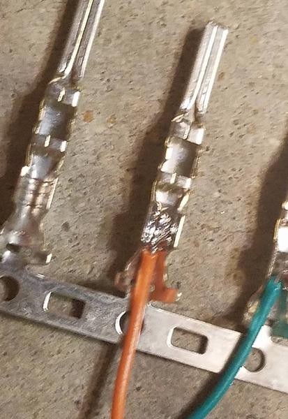 Soldered Wire to Connector Pin
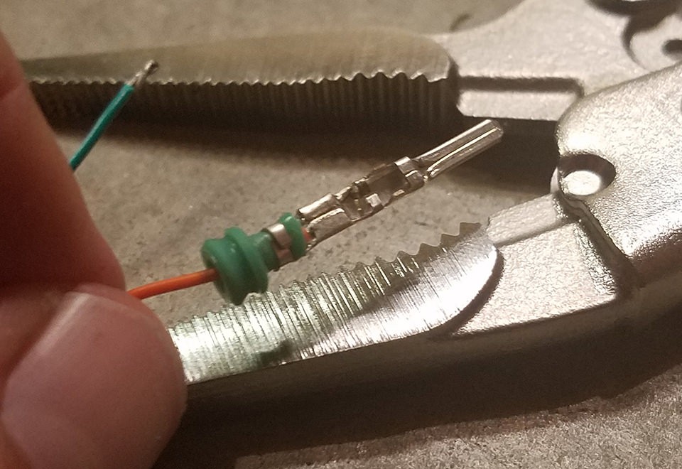
Step 5: Crimping the Pins (Alternative Method)
If you don’t have a soldering iron or prefer not to solder, you can crimp the pins onto the wires. A Molex crimping tool is ideal for this, but needle-nose pliers can be used with care.
- Using a Crimping Tool (Recommended): If you have a Molex crimping tool, use the appropriate setting for the pin size and wire gauge. Place the pin in the tool, insert the wire, and crimp firmly to secure the wire.
- Using Needle-Nose Pliers (Alternative): If using pliers, carefully fold one of the wire-gripping prongs over the wire using the pliers at an angle.
- Repeat for the other wire-gripping prong, ensuring a tight crimp that securely holds the wire.
- For added security (optional), you can gently squeeze the crimped prongs further with the pliers to ensure a very tight mechanical connection. Be careful not to damage the pin. Refer to online videos like this one on YouTube for crimping techniques using pliers.
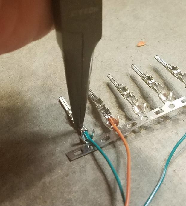 Crimping Connector Pin with Pliers
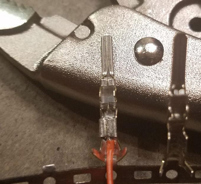 Crimped Connector Pin Detail
Step 6: Crimp the Seal-Gripping Prongs
After securing the wire, the next step is to crimp the second set of prongs over the rubber seal to provide strain relief and environmental protection.
- Slide the rubber seal up the wire until it sits between the second set of prongs (the seal-gripping prongs) on the connector pin.
- Use the same crimping technique as before (either with a crimping tool or needle-nose pliers) to fold these prongs over the rubber seal. This secures the seal and provides strain relief to the wire connection.
 Crimping Seal-Gripping Prongs
 Seal-Gripping Prongs Crimped
 Completed Pin with Wire and Seal Crimped
Step 7: Wire Pairing and Twisting (Recommended)
Although the exact reason isn’t definitively stated, it’s often recommended in similar DIY guides to twist certain pairs of wires together. This may help reduce electromagnetic interference and improve signal integrity.
Pair the wires as follows and twist them together:
- Pin 4 (orange wire) / Pin 16 (green/white stripe wire) – Twist these two wires together.
- Pin 6 (green wire) / Pin 14 (brown/white stripe wire) – Twist these two wires together.
Unfortunately, there isn’t an image specifically showing the twisted wire pairs.
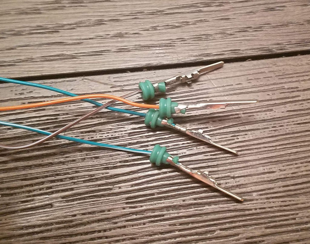
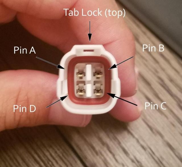
Step 8: Insert Pins into the 4-Pin Connector Housing
The final step is to insert the completed pins into the 4-pin connector housing in the correct orientation. Refer to the diagram and pin assignments below.
Insert the pins into the back of the 4-pin connector housing in the following positions:
- Pin 14 (brown/white stripe wire): Insert into connector slot A.
- Pin 6 (green wire): Insert into connector slot B.
- Pin 16 (green/white stripe wire): Insert into connector slot C.
- Pin 4 (orange wire): Insert into connector slot D.
Push each pin in from the rear of the connector until you hear a click. This click indicates that the pin is locked securely in place. You can use needle-nose pliers to gently pull on the wire from the back to ensure the pin is properly locked and won’t come out.
 4-Pin Connector Pin Insertion
Testing Your 4 Pin to OBD2 Adapter
Congratulations! You have now built your 4 pin to OBD2 adapter cable.
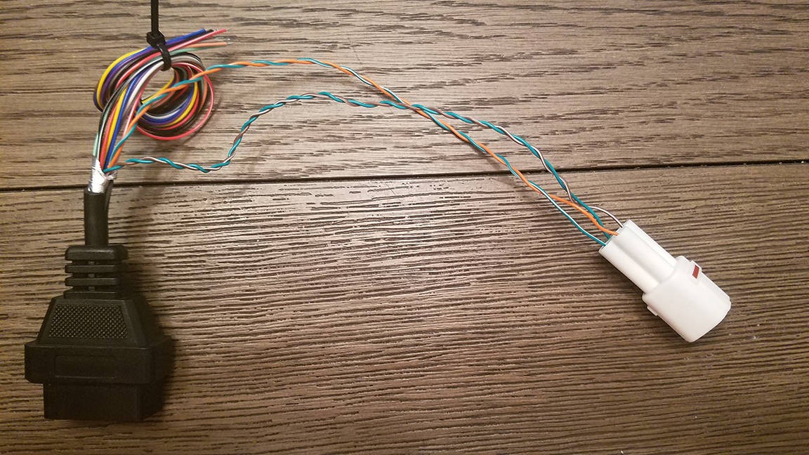 Completed 4 Pin to OBD2 Adapter
 Completed Adapter Cable Ends
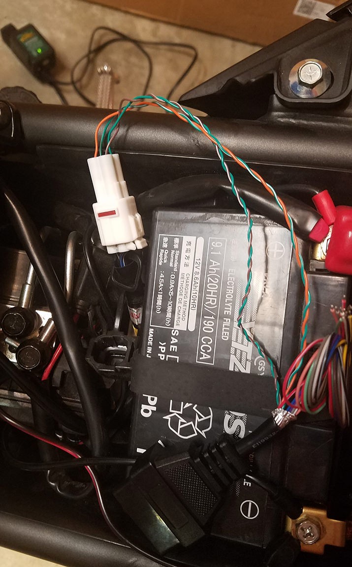
To test your adapter, connect it between your vehicle’s 4-pin diagnostic port and your OBD2 scanner. Turn on your vehicle’s ignition and then your OBD2 scanner. Attempt to read diagnostic codes or perform other scanner functions.
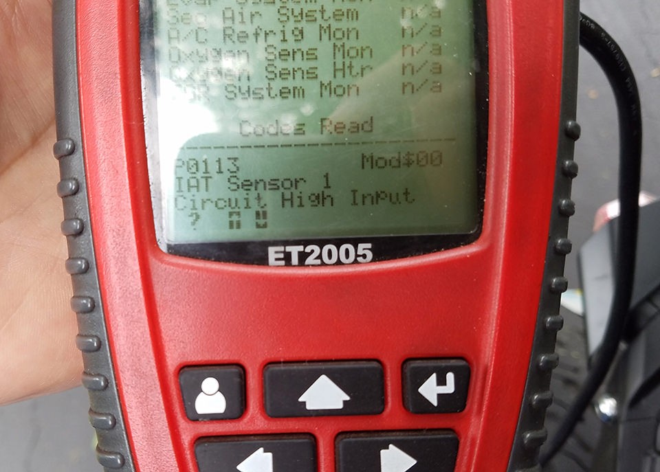 Testing the Adapter with an OBD2 Scanner
If everything is wired correctly, your scanner should now be able to communicate with your vehicle’s computer system, allowing you to diagnose and troubleshoot issues.
If you encounter any issues or have questions, double-check your wiring against this guide and the pinout diagrams. If you’re still unsure, seek assistance from online automotive forums or a qualified mechanic.