Since 1996, all cars and light trucks sold in the United States have been mandated to be OBD-II compliant. European OBD legislation, while having its own nuances, also ensures similar standards for vehicles within the European Union. Understanding OBD-II protocols is crucial for anyone involved in vehicle diagnostics and repair, from professional technicians to car enthusiasts performing DIY maintenance. This guide will delve into the world of OBD2 protocols, explaining the different types and how they relate to your vehicle’s make and model.
Understanding OBD2 Protocols
OBD-II, or On-Board Diagnostics II, is a standardized system that allows access to vehicle subsystem information for diagnostics purposes. This standardization is critical, meaning regardless of the vehicle manufacturer, there’s a common way to communicate with the vehicle’s computer. However, while the communication interface is standardized (the OBD2 port), the language or protocol used over this interface can vary.
Common OBD2 Protocols
There are five primary communication protocols used in OBD-II compliant vehicles:
- J1850 PWM (Pulse Width Modulation): This protocol, defined by SAE standard J1850, was commonly used by Ford vehicles. It is characterized by pin 2 and pin 10 presence in the DLC connector.
- J1850 VPW (Variable Pulse Width): Another SAE J1850 protocol, primarily used by General Motors vehicles. This protocol is identified by the presence of pin 2 but the absence of pin 10 in the DLC.
- ISO9141-2: An international standard protocol widely adopted by Chrysler and European vehicles. ISO9141-2 systems utilize pin 7 (K-line) and may or may not use pin 15 (L-line).
- ISO14230-4 (KWP2000 – Keyword Protocol 2000): Also an ISO standard, KWP2000 is similar to ISO9141-2 and was used by a range of manufacturers, particularly for vehicles transitioning to CAN. It also uses pin 7 (K-line) and optionally pin 15 (L-line).
- ISO15765-4/SAE J2480 (CAN – Controller Area Network): The most modern and prevalent protocol, CAN bus is now mandatory for all vehicles manufactured from model year 2008 onwards. Before 2003, US manufacturers were restricted from using CAN. CAN protocol uses pins 6 (CAN High) and 14 (CAN Low) in the DLC.
OBD2 Connector Types and Location
The physical interface for accessing these protocols is the Diagnostic Link Connector (DLC). SAE J1962 defines two types of DLC connectors: Type A and Type B. The key difference is the alignment tab shape, ensuring proper connection.
Type A DLCs are typically found inside the passenger or driver’s compartment, within easy reach of the driver’s seat, often under the instrument panel, between the steering column and the vehicle’s center line.
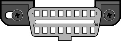 J1962F, Type A
Fig. 1 – OBD2 Type A connector diagram, showing the standard J1962 Type A DLC for vehicle diagnostics.
Type B DLCs are also in the passenger or driver’s compartment, mounted to the instrument panel for easy access, but their location can extend further from the vehicle’s centerline and might be accessible from the co-driver’s seat or even outside the vehicle.
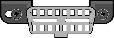 J1962F, Type B
Fig. 2 – OBD2 Type B connector diagram, illustrating the J1962 Type B DLC often found in commercial vehicles.
Identifying Your Vehicle’s OBD2 Protocol
A quick way to get an initial indication of your vehicle’s OBD2 protocol is to examine the pinout of the DLC connector. By checking which pins are populated, you can narrow down the possibilities. Crucially, all OBD2 connectors must have pins 4 (Chassis Ground), 5 (Signal Ground), and 16 (Battery Positive).
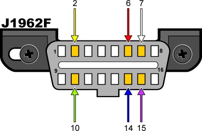 J1962F OBDII connector pinout
Fig. 3 – OBD2 connector pinout diagram, detailing pin assignments for identifying OBD2 communication protocols like CAN, ISO, J1850 PWM, and J1850 VPW.
Here’s a table summarizing how pin presence correlates with the protocol type:
| Pin 2 | Pin 6 | Pin 7 | Pin 10 | Pin 14 | Pin 15 | Protocol |
|---|---|---|---|---|---|---|
| Must | – | – | Must | – | – | J1850 PWM |
| Must | – | – | – | – | – | J1850 VPW |
| – | – | Must | – | – | May* | ISO9141/14230 |
| – | Must | – | – | Must | – | ISO15765 (CAN) |
*Pin 15 (L-line) is optional in newer ISO9141-2 or ISO14230-4 vehicles.
Therefore:
- PWM: Pins 2, 4, 5, 10, and 16 are present.
- VPW: Pins 2, 4, 5, and 16 are present, but pin 10 is absent.
- ISO: Pins 4, 5, 7, and 16 are present; pin 15 may or may not be present.
- CAN: Pins 4, 5, 6, 14, and 16 are present.
While pinout provides a strong indication, for definitive confirmation of the OBD2 protocol used by your specific vehicle make and model, especially when considering model year variations and manufacturer-specific implementations, consulting resources that detail “OBDII Generic Communication Protocols by Manufacturer” can be invaluable. These resources bridge the gap between general OBD2 standards and the specifics of vehicle makes and models, ensuring accurate diagnostics and communication.