The On-Board Diagnostics version 2 (OBD2) system is a cornerstone of modern vehicle maintenance and repair. It acts as your car’s internal health monitor, providing crucial insights into its operation. At the heart of this system, the Controller Area Network (CAN) bus plays a vital role, enabling communication and data exchange. This guide offers a detailed exploration into Can Obd2, explaining everything from its basic principles to advanced applications, ensuring you grasp how this technology empowers vehicle diagnostics.
Whether you’re a car enthusiast, a professional mechanic, or simply curious about your vehicle’s inner workings, understanding can obd2 is invaluable. This practical introduction will cover the OBD2 connector, Parameter IDs (PIDs), and their critical link to the CAN bus network. You’ll learn how to request and interpret OBD2 data, explore key use cases for data logging, and gain practical tips to effectively utilize this powerful diagnostic tool. Let’s delve into why this has become a go-to resource for understanding OBD2 technology.
What is OBD2 and How Does It Work?
OBD2 is essentially your car’s self-diagnostic system built right in. It’s a standardized protocol that makes it possible to retrieve diagnostic trouble codes (DTCs) and access real-time operational data through the OBD2 connector.
You’ve likely already encountered OBD2 in action without realizing it. Have you ever seen the malfunction indicator light, often referred to as the “check engine light,” illuminate on your dashboard?
That light is your car signaling that it has detected a problem. When you take your vehicle to a mechanic, they will typically use an OBD2 scanner to pinpoint the issue.
To do this, the mechanic connects the OBD2 reader to the OBD2 16-pin connector, usually located near the steering wheel. The diagnostic tool sends ‘OBD2 requests’ to the car’s computer system. In turn, the car responds with ‘OBD2 responses’, which can include information like speed, fuel level, and, importantly, Diagnostic Trouble Codes (DTCs). This communication process, heavily reliant on can obd2 principles, allows for quicker and more accurate troubleshooting of vehicle problems.
OBD2 Compatibility: Does Your Car Have It?
The simple answer is: Almost certainly!
The vast majority of modern, non-electric vehicles are equipped with OBD2 systems, and most of these systems operate using the CAN bus protocol. However, for older vehicles, it’s worth noting that the presence of a 16-pin OBD2 connector doesn’t automatically guarantee OBD2 support. Some older models may have the connector but not fully implement the OBD2 standard. A reliable way to confirm OBD2 compliance is to consider where and when your car was initially purchased:
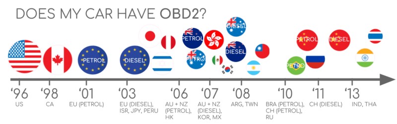
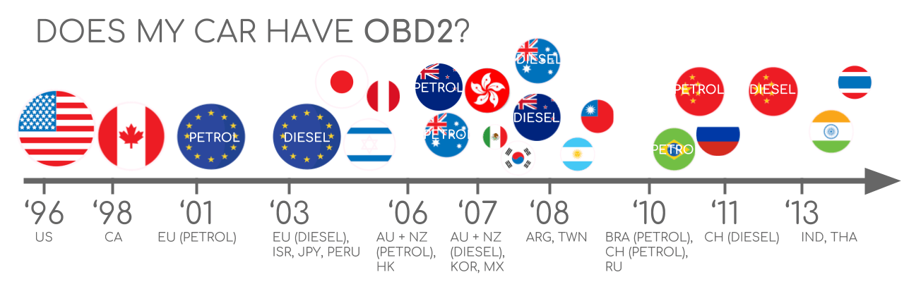 Does My Car Have OBD2?
Generally, if your car was bought new in the United States after 1996, in the European Union after 2001 (for gasoline cars) or 2004 (for diesel cars), it is highly likely to be OBD2 compliant. This widespread adoption underscores the importance of can obd2 in vehicle manufacturing and diagnostics globally.
A Brief History of OBD2 Development
The story of OBD2 begins in California, driven by the California Air Resources Board (CARB). In their pursuit of improved emission control, CARB mandated the inclusion of On-Board Diagnostics in all new cars sold in California starting from 1991.
The OBD2 standard we know today was largely shaped by recommendations from the Society of Automotive Engineers (SAE). They standardized Diagnostic Trouble Codes (DTCs) and the physical OBD connector across all vehicle manufacturers with the SAE J1962 standard. This move towards standardization was crucial for the widespread adoption and effectiveness of can obd2 systems.
From its Californian origins, the OBD2 standard progressively rolled out across the United States and Europe:
- 1996: OBD2 became mandatory in the USA for all cars and light trucks.
- 2001: The European Union mandated OBD2 for gasoline cars.
- 2003: OBD2 requirements extended in the EU to include diesel cars (known as EOBD in Europe).
- 2005: OBD2 was required in the US for medium-duty vehicles.
- 2008: US regulations stipulated that all cars must use ISO 15765-4 (CAN) as the foundation for OBD2 communication, solidifying the role of can obd2.
- 2010: Finally, OBD2 compliance was mandated in the US for heavy-duty vehicles.
This phased implementation reflects the growing importance of standardized vehicle diagnostics and the pivotal role of can obd2 in achieving this.
The Future of OBD2: Trends and Challenges
OBD2 is expected to remain a vital part of vehicle technology, but its future form is evolving.
Initially designed for emissions control and testing, legislated OBD2 requirements have not been uniformly applied to electric vehicles. Interestingly, most modern EVs do not support standard OBD2 requests. Instead, they often employ OEM-specific UDS communication protocols. This shift can make accessing data from electric vehicles challenging, unless decoding methods are reverse-engineered. However, there are successful cases of reverse engineering, allowing access to data from brands like Tesla, Hyundai/Kia, Nissan, and VW/Skoda EVs.
Recognizing the limitations of current OBD2 implementations in terms of data richness and protocol flexibility, modern alternatives have emerged. These include WWH-OBD (World Wide Harmonized OBD) and OBDonUDS (OBD on UDS). Both are designed to enhance and streamline OBD communication by using the UDS protocol as a base. These advancements point towards a future where can obd2 principles are adapted and integrated with newer communication standards to meet evolving vehicle technology.
In our increasingly connected world, traditional OBD2 testing methods are becoming less efficient. Manual emission checks are time-consuming and costly.
The proposed solution is OBD3 – the integration of telematics into all vehicles.
OBD3 envisions equipping every car with a small radio transponder, similar to those used for bridge tolls. This would allow for the vehicle identification number (VIN) and DTCs to be transmitted wirelessly via WiFi to a central server for automated checks.
Many current devices already facilitate the transfer of CAN or OBD2 data over WiFi or cellular networks, such as the CANedge2 WiFi CAN logger and the CANedge3 3G/4G CAN logger. While this offers convenience and cost savings, it also raises political concerns regarding surveillance and data privacy.
The original purpose of OBD2 was for stationary emission controls. Yet, today, it’s extensively used by third parties to generate real-time vehicle data through OBD2 dongles, CAN loggers, and similar devices. However, the German car industry is pushing for changes that could limit this third-party access.
BMW, among others, argues that OBD2 was intended for repair shop servicing, not for creating a data-driven economy based on third-party access. The proposal suggests disabling OBD2 functionality during normal driving, with data collection centralized through manufacturer servers. This would give vehicle manufacturers control over ‘automotive big data’.
Arguments for this shift include enhanced security, aiming to reduce the risk of car hacking. However, many perceive this as a commercially motivated move to control valuable vehicle data. Whether this trend will take hold remains to be seen, but it has the potential to significantly disrupt the market for third-party can obd2 services.
Get our ‘Ultimate CAN Guide’
Want to become a CAN bus expert?
Get our 12 ‘simple intros’ in one 160+ page PDF:
Download now
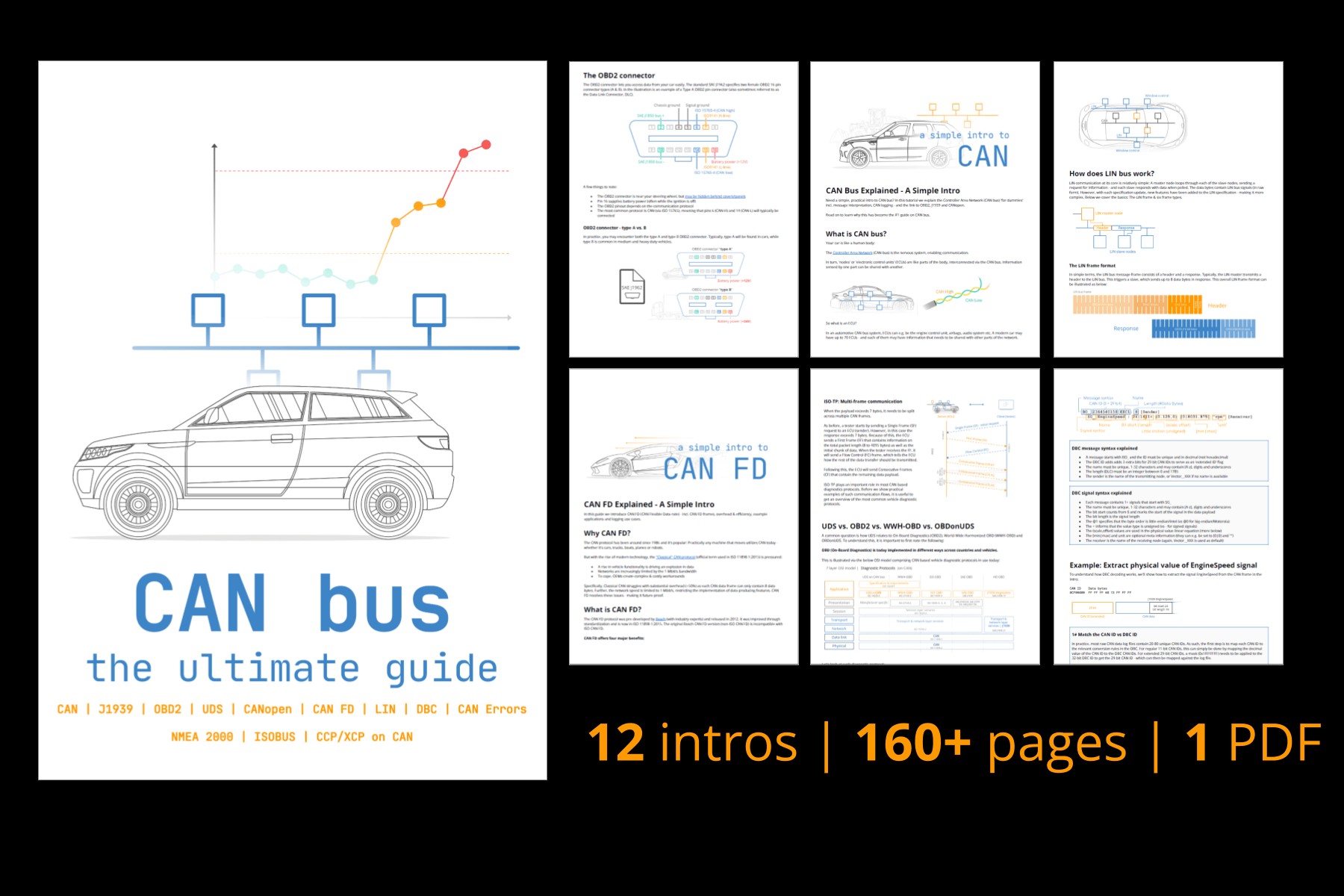 CAN Bus – The Ultimate Guide Tutorial PDF
OBD2 Standards and Protocols
On-board diagnostics, OBD2, operates as a higher layer protocol, much like a language spoken over a communication network. CAN (Controller Area Network) bus, in this context, is the communication method, similar to a telephone line. This analogy positions OBD2 alongside other CAN-based higher-layer protocols such as J1939, CANopen, and NMEA 2000.
Specifically, OBD2 standards define the OBD2 connector, the lower-layer communication protocols, OBD2 Parameter IDs (PIDs), and more. These standards are meticulously structured, often visualized using the 7-layer OSI model to categorize the different aspects of communication. In the following sections, we will focus on the most critical standards within this framework, particularly those relevant to can obd2 implementation.
Looking at the OSI model, you’ll notice that both SAE (Society of Automotive Engineers) and ISO (International Organization for Standardization) standards cover multiple layers. This dual coverage reflects the development of OBD standards in both the USA (SAE) and Europe (ISO). Many of these standards are technically very similar; for instance, SAE J1979 is almost equivalent to ISO 15031-5, and SAE J1962 closely mirrors ISO 15031-3. This alignment ensures a degree of global compatibility in can obd2 systems.
The OBD2 Connector [SAE J1962]
The 16-pin OBD2 connector is your physical gateway to accessing vehicle data, standardized under SAE J1962 / ISO 15031-3. This connector, sometimes referred to as the Data Link Connector (DLC), is designed for easy access to your vehicle’s diagnostic information, especially within can obd2 systems.
The illustration above shows a typical Type A OBD2 pin connector. Here are some key points about it:
- The connector is usually located near the steering wheel, but it might be hidden from plain sight under the dashboard.
- Pin 16 provides battery power, often even when the ignition is turned off, ensuring constant power supply for certain diagnostic functions.
- The specific OBD2 pinout arrangement is protocol-dependent, meaning the function of each pin can vary based on the communication protocol used.
- For can obd2 systems, the most common lower-layer protocol is CAN bus, which means pins 6 (CAN-High) and 14 (CAN-Low) are typically the communication lines.
OBD2 Connector – Type A vs. B
You may encounter both Type A and Type B OBD2 connectors in practice. Type A is predominantly used in cars and light vehicles, while Type B is more common in medium and heavy-duty vehicles. The distinction between these types is important for ensuring compatibility when connecting diagnostic equipment to can obd2 systems.
As illustrated, both connector types share a similar pinout structure but differ primarily in their power supply outputs: Type A typically provides 12V, while Type B is designed for 24V systems. Baud rates can also vary; cars commonly use 500K, whereas heavy-duty vehicles often use 250K (although 500K support is becoming more frequent).
A physical difference helps distinguish between them: the Type B OBD2 connector has a distinctive interrupted groove in the middle. Consequently, a Type B OBD2 adapter cable is versatile and compatible with both Type A and Type B sockets, whereas a Type A adapter will only fit into a Type A socket. Understanding these connector types is crucial for anyone working with can obd2 in diverse vehicle applications.
Can OBD2 Communication: ISO 15765-4
Since 2008, CAN bus has been mandated as the lower-layer protocol for OBD2 in all vehicles sold in the US, according to ISO 15765. This standardization cemented the importance of can obd2 as the primary communication method for vehicle diagnostics.
ISO 15765-4, also known as Diagnostics over CAN (or DoCAN), specifies a set of constraints and guidelines applied to the CAN standard (ISO 11898) to ensure reliable diagnostic communication. It standardizes the CAN interface for diagnostic test equipment, focusing on the physical, data link, and network layers of the OSI model.
Key specifications under ISO 15765-4 for can obd2 include:
- The CAN bus bit-rate must be either 250 Kbit/s or 500 Kbit/s.
- Both 11-bit and 29-bit CAN identifiers are permitted.
- Specific CAN IDs are designated for OBD requests and responses to ensure proper routing and interpretation of diagnostic messages.
- The diagnostic CAN frame data length is fixed at 8 bytes to maintain consistency and predictability in data handling.
- The OBD2 adapter cable connecting diagnostic tools to the vehicle must not exceed 5 meters in length to minimize signal degradation and maintain communication integrity.
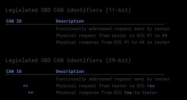
OBD2 CAN Identifiers (11-bit, 29-bit)
All OBD2 communication over CAN bus relies on a request-response message exchange. Understanding the CAN identifiers used in can obd2 is crucial for interpreting the data flow.
In most passenger cars, 11-bit CAN IDs are used for OBD2 communication. Here, the ‘Functional Addressing’ ID is 0x7DF. This ID is used when a diagnostic tool broadcasts a request to all OBD2-compliant Electronic Control Units (ECUs) in the vehicle, asking if they have data to report for the requested parameter, as per ISO 15765-4. In contrast, CAN IDs in the range 0x7E0 to 0x7E7 are reserved for ‘Physical Addressing’ requests. These are used to target specific ECUs, although they are less commonly used in typical OBD2 diagnostics.
ECUs respond to requests using 11-bit IDs in the range 0x7E8 to 0x7EF. The most frequently used response ID is 0x7E8, which typically comes from the ECM (Engine Control Module). Another common response ID is 0x7E9, often used by the TCM (Transmission Control Module).
In some types of vehicles, particularly vans and light, medium, and heavy-duty vehicles, OBD2 communication may utilize extended 29-bit CAN identifiers instead of the standard 11-bit IDs. This is another facet of can obd2 that varies across vehicle types.
For 29-bit CAN, the ‘Functional Addressing’ CAN ID is 0x18DB33F1.
When a vehicle responds using 29-bit identifiers, the response IDs fall within the range 0x18DAF100 to 0x18DAF1FF, with typical examples being 0x18DAF110 and 0x18DAF11E. These response IDs are sometimes also represented in the ‘J1939 PGN’ format. Specifically, PGN 0xDA00 (55808) is designated in the J1939-71 standard as ‘Reserved for ISO 15765-2’, further linking can obd2 to broader automotive communication standards.
 OBD2 OBD CAN bus Identifiers 7DF 7E8 7E0
OBD2 vs. Proprietary CAN Protocols
It’s important to understand that your vehicle’s Electronic Control Units (ECUs) operate primarily using proprietary CAN protocols defined by the vehicle manufacturer, not OBD2. OBD2 is implemented as a secondary diagnostic system that works in parallel with these OEM-specific protocols. These proprietary CAN protocols are often unique to each vehicle brand, model, and year, and understanding them typically requires in-depth, OEM-specific knowledge, or reverse engineering efforts. This distinction is crucial when discussing can obd2 in the context of overall vehicle communication.
If you connect a CAN bus data logger to your car’s OBD2 connector, you might observe OEM-specific CAN data alongside OBD2 data. This OEM-specific data is usually broadcast at a high rate, around 1000-2000 frames per second, and contains detailed operational data used by the vehicle’s systems. However, in many newer vehicles, a ‘gateway’ module is implemented to filter and control access to this CAN data through the OBD2 port. This gateway often restricts access to the proprietary CAN data and primarily facilitates OBD2 communication.
In essence, think of OBD2 as an additional, higher-layer protocol that exists alongside the OEM-specific protocol within your vehicle’s communication network. Both utilize the CAN bus, but they serve different purposes and may have restricted access, particularly in modern vehicles. This parallel existence is a key aspect of can obd2 in contemporary automotive systems.
Bit-rate and ID Validation
As previously mentioned, OBD2 over CAN can operate with two different bit-rates (250 Kbit/s, 500 Kbit/s) and two CAN ID lengths (11-bit, 29-bit), resulting in four possible combinations. In modern cars, the 500 Kbit/s bit-rate with 11-bit IDs is the most common configuration, but diagnostic tools need to systematically determine the correct combination for each vehicle to ensure proper can obd2 communication.
ISO 15765-4 provides a standardized initialization sequence to automatically identify the correct bit-rate and CAN ID configuration. This process is illustrated in the flowchart below. The method relies on the fact that all OBD2-compliant vehicles must respond to a specific mandatory OBD2 request (detailed in the OBD2 PID section). It also takes advantage of the principle that transmitting CAN data with an incorrect bit-rate will result in CAN error frames, which can be detected by diagnostic tools.
Updated versions of ISO 15765-4 account for vehicles that may support OBD communication via OBDonUDS (OBD on Unified Diagnostic Services) instead of the more traditional OBDonEDS (OBD on Emission Diagnostic Service). This article primarily focuses on OBD2/OBDonEDS, which aligns with standards like ISO 15031-5/SAE J1979. WWH-OBD/OBDonUDS, based on ISO 14229 and ISO 27145-3/SAE J1979-2, is more commonly found in EU trucks and buses.
To distinguish between OBDonEDS and OBDonUDS protocols, a diagnostic tool can send additional request messages. Specifically, it can send UDS requests using 11-bit or 29-bit functional address IDs for service 0x22 and data identifier (DID) 0xF810 (protocol identification). Vehicles supporting OBDonUDS are required to have ECUs that respond to this DID, allowing the diagnostic tool to identify the protocol in use. Understanding these nuances is key to effectively interacting with different can obd2 implementations.
In practice, OBDonEDS (also referred to as OBD2, SAE OBD, EOBD, or ISO OBD) is prevalent in most non-electric vehicles today, while WWH-OBD is primarily used in European heavy-duty vehicles.
Five Lower-Layer OBD2 Protocols
While CAN (ISO 15765) is the dominant lower-layer protocol for OBD2 in the vast majority of modern vehicles, particularly those manufactured post-2008, older vehicles may utilize one of four other lower-layer protocols. When working with older cars (pre-2008), it’s helpful to be aware of these alternative protocols, as well as their corresponding OBD2 connector pinouts, which can sometimes help determine the protocol in use. Even though CAN is now standard for can obd2, these older protocols represent the evolution of vehicle diagnostics.
The five lower-layer protocols used for OBD2 are:
- ISO 15765 (CAN bus): Mandatory in US cars since 2008 and now the most widely used protocol globally.
- ISO 14230-4 (KWP2000): Keyword Protocol 2000, commonly used in cars from 2003 onwards, particularly in Asian markets.
- ISO 9141-2: Used in European, Chrysler, and Asian cars manufactured between 2000 and 2004.
- SAE J1850 (VPW – Variable Pulse Width Modulation): Primarily found in older General Motors (GM) vehicles.
- SAE J1850 (PWM – Pulse Width Modulation): Mostly used in older Ford vehicles.
Transporting OBD2 Messages via ISO-TP [ISO 15765-2]
All OBD2 data communication over CAN bus is managed by a transport protocol known as ISO-TP (ISO 15765-2). This protocol is essential because it enables the transmission of data payloads larger than the standard 8-byte limit of a single CAN frame. This capability is necessary in OBD2 for operations like retrieving the Vehicle Identification Number (VIN) or Diagnostic Trouble Codes (DTCs), which often require more than 8 bytes of data. ISO 15765-2 handles this by providing mechanisms for segmentation, flow control, and reassembly of larger messages, ensuring reliable can obd2 data transfer. For a more detailed understanding of ISO-TP’s functionalities, refer to our introduction to UDS.
However, much of the OBD2 data exchanged in routine diagnostics fits within a single CAN frame. In these cases, ISO 15765-2 specifies the use of a ‘Single Frame’ (SF) format. In a Single Frame, the first data byte (known as the PCI field – Protocol Control Information) indicates the payload length, excluding any padding. This leaves 7 bytes within the CAN frame data field available for the actual OBD2-related communication. This efficient use of CAN frames is a key aspect of practical can obd2 implementation.
The OBD2 Diagnostic Message [SAE J1979, ISO 15031-5]
To gain a deeper understanding of can obd2 communication, let’s examine the structure of a raw ‘Single Frame’ OBD2 CAN message. In simplified terms, an OBD2 message consists of a CAN identifier, a data length indicator (PCI field), and the actual data payload. The data payload itself is further structured into components: Mode, parameter ID (PID), and data bytes.
Example: OBD2 Request/Response
Before dissecting each component of the OBD2 message, let’s consider a practical example: a request for and response to the ‘Vehicle Speed’ parameter. This example will illustrate how can obd2 messages are structured and exchanged.
In this scenario, an external diagnostic tool initiates a request to the vehicle by sending a CAN message with the ID 0x7DF and a 2-byte payload. The payload contains: Mode 0x01 and PID 0x0D. This is a standard OBD2 request for real-time data (Mode 0x01) and specifically for Vehicle Speed (PID 0x0D).
In response, the car sends back a CAN message with the ID 0x7E8 and a 3-byte payload. This payload includes the value of Vehicle Speed in the 4th byte of the original CAN data frame, represented as 0x32 (which is 50 in decimal form).
By consulting the OBD2 PID documentation for PID 0x0D, we can determine the decoding rules. In this case, 0x32 corresponds to a physical value of 50 km/h. This simple exchange demonstrates the fundamental request-response mechanism in can obd2 and how data is encoded and interpreted.
The 10 OBD2 Services (aka Modes)
OBD2 defines 10 diagnostic services, often referred to as ‘modes’. Each mode serves a specific purpose in vehicle diagnostics. For example, Mode 0x01 is used to retrieve current, real-time data parameters, while other modes are designed to access or clear diagnostic trouble codes (DTCs) or to retrieve freeze frame data. Understanding these modes is essential for effectively using can obd2 for vehicle diagnostics.
It’s important to note that vehicles are not required to support all 10 OBD2 modes. Moreover, manufacturers may implement additional, non-standardized modes beyond these 10 for OEM-specific diagnostics.
In OBD2 messages, the mode is identified in the second byte of the data payload. In a request message, the mode is included directly (e.g., 0x01). However, in a response message, 0x40 is added to the requested mode value (e.g., a response to mode 0x01 will start with 0x41). This convention helps in easily distinguishing between requests and responses in can obd2 communication traces.
OBD2 Parameter IDs (PIDs)
Within each OBD2 mode, Parameter IDs (PIDs) are used to specify the particular data parameter being requested or reported. PIDs are integral to the functionality of can obd2, allowing for precise data retrieval.
For instance, Mode 0x01, which is for showing current data, includes approximately 200 standardized PIDs. These PIDs cover a wide range of real-time data parameters, such as vehicle speed, engine RPM, and fuel level. However, it’s crucial to know that a vehicle is not obligated to support all defined OBD2 PIDs within a mode. In practice, most vehicles only support a subset of the available PIDs. The specific PIDs supported can vary based on vehicle make, model, and year.
In this context, one PID holds a special significance: PID 0x00 in Mode 0x01. If an emissions-related ECU in a vehicle supports any OBD2 services at all, it must support Mode 0x01 PID 0x00. When this PID is requested, the vehicle ECU responds by indicating which PIDs in the range 0x01-0x20 it supports. This makes PID 0x00 a fundamental tool for an ‘OBD2 compatibility test’. Furthermore, PIDs 0x20, 0x40, 0x60, 0x80, 0xA0, and 0xC0 serve a similar purpose, each revealing support for subsequent blocks of PIDs within Mode 0x01 (PIDs 0x21-0x40, 0x41-0x60, and so on). These PIDs are essential for dynamically determining the data parameters available from a vehicle’s can obd2 system.
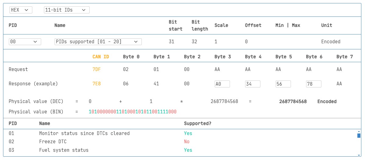 OBD2 PID overview tool
Tip: OBD2 PID Overview Tool
The appendices of SAE J1979 and ISO 15031-5 contain detailed scaling information for standard OBD2 PIDs. This information is crucial for decoding the raw data bytes received from a vehicle into meaningful physical values, as explained in our CAN bus introduction. Having access to this scaling data is vital for anyone working with can obd2 data.
If you need to quickly look up a Mode 0x01 PID, our OBD2 PID overview tool is a valuable resource. This tool helps you construct OBD2 request frames and dynamically decode OBD2 responses, streamlining the process of working with can obd2 data.
OBD2 PID overview tool
Practical Guide: How to Log and Decode Can OBD2 Data
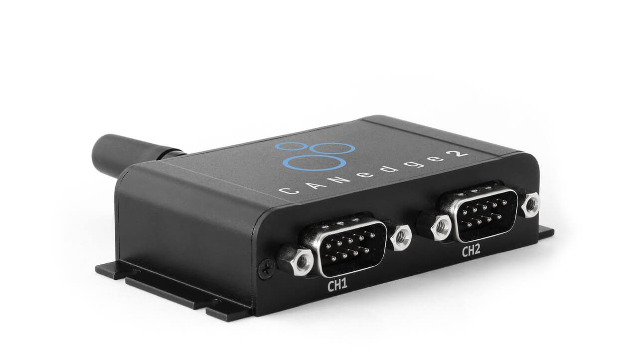
In this section, we’ll walk through a practical example of how to log OBD2 data using the CANedge CAN bus data logger. The CANedge is designed to be highly configurable, allowing you to define custom CAN frames for transmission. This capability makes it exceptionally well-suited for OBD2 logging and interacting with can obd2 systems.
Once configured, the CANedge device can be easily connected to your vehicle using our OBD2-DB9 adapter cable. This setup provides a straightforward way to start capturing and analyzing can obd2 data.
 OBD2 bit rate test You can send a CAN frame at e.g. 500K, then check if it is successfully sent
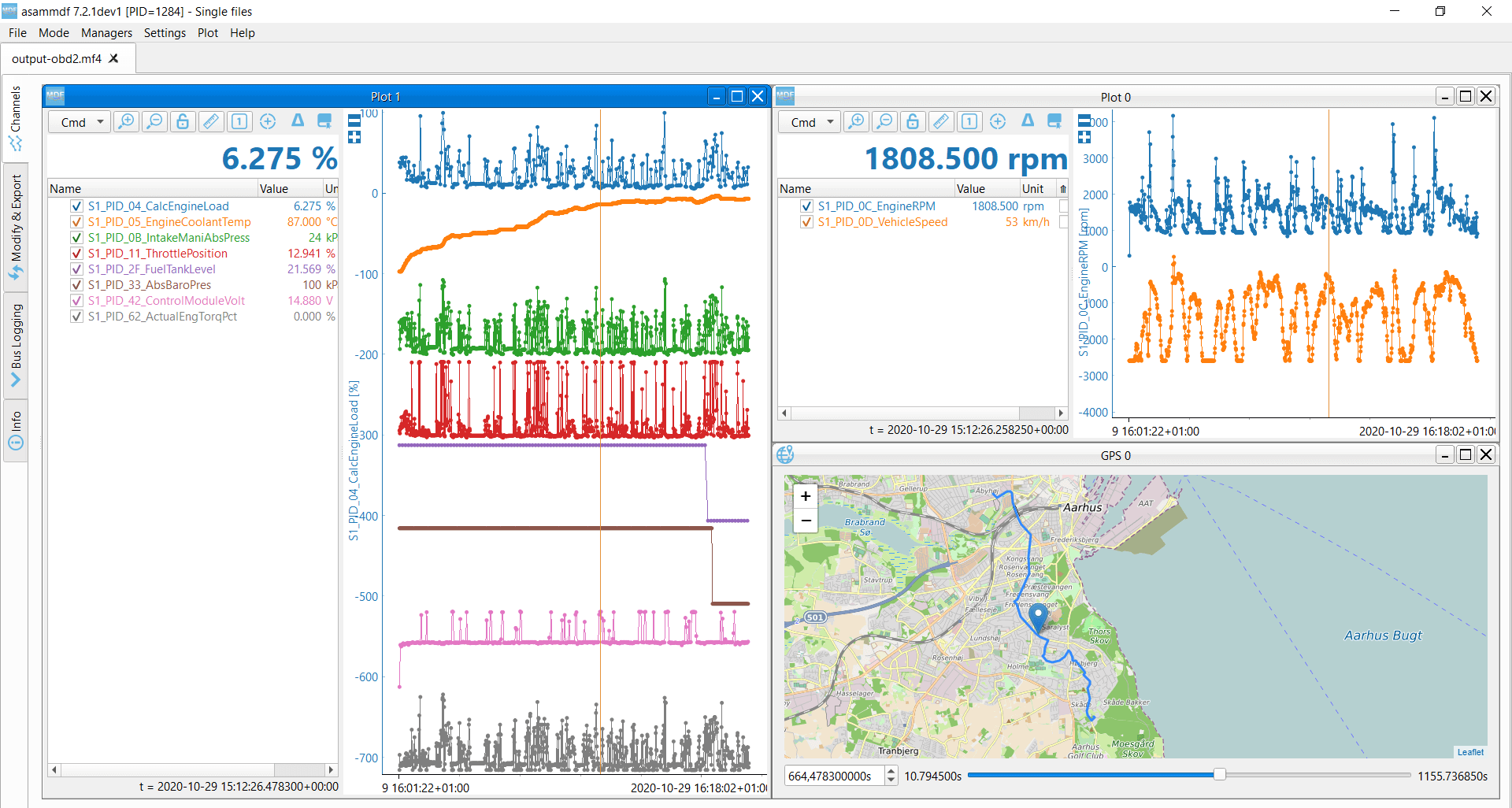
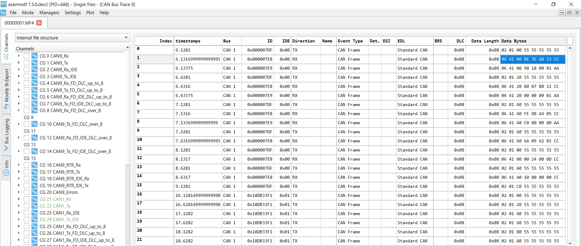 OBD2 Supported PIDs Test The responses to ‘Supported PIDs’ can be reviewed in asammdf
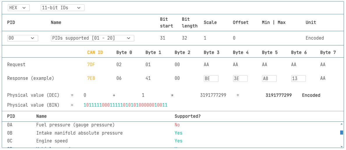 Review supported PIDs via OBD2 lookup tool
#1: Test Bit-rate, IDs & Supported PIDs
As discussed earlier, ISO 15765-4 outlines a procedure to determine the correct bit-rate and CAN IDs used by a specific vehicle for can obd2 communication. You can use the CANedge to perform these tests as follows (refer to the CANedge Intro for detailed instructions):
- Test Bit-rate: Begin by sending a CAN frame at 500 Kbit/s. Check if the transmission is successful. If not, try 250 Kbit/s. Successful transmission at one of these rates indicates the correct bit-rate for can obd2 communication with the vehicle.
- Use Identified Bit-rate: Once you’ve determined the correct bit-rate, use it for all subsequent communication.
- Send ‘Supported PIDs’ Requests: Send multiple ‘Supported PIDs’ requests (Mode 0x01, PID 0x00 and potentially 0x20, 0x40, etc.) to discover which PIDs the vehicle supports.
- Review Responses: Analyze the response IDs to determine whether the vehicle is using 11-bit or 29-bit CAN IDs for can obd2 communication.
- Determine Supported PIDs: Examine the response data to identify the specific PIDs supported by the vehicle. Our OBD2 PID lookup tool can be invaluable for decoding these responses.
We provide pre-configured settings to simplify these initial tests, making it easier to validate your can obd2 setup.
Most non-electric vehicles manufactured in 2008 or later typically support between 40 to 80 PIDs, using a 500 Kbit/s bit-rate, 11-bit CAN IDs, and the OBD2/OBDonEDS protocol.
As illustrated in the asammdf GUI screenshot, it’s common to receive multiple responses to a single OBD request. This is because we use the functional address request ID 0x7DF, which prompts all ECUs to respond if they have relevant data. Since all OBD2/OBDonEDS-compliant ECUs are required to support service 0x01 PID 0x00, you often see numerous responses to this PID in particular. As you proceed to request subsequent ‘Supported PIDs’, fewer ECUs may respond, as shown in the example. Notice that the ECM ECU (0x7E8) in the example supports all the PIDs that are supported by any other ECU in the vehicle. This observation suggests that you could potentially reduce bus load by directing subsequent requests specifically to the ECM (using the ‘Physical Addressing’ CAN ID 0x7E0) rather than broadcasting to all ECUs.
#2: Configure OBD2 PID Requests
After determining the supported OBD2 PIDs for your vehicle and the correct bit-rate and CAN IDs to use, the next step is to configure your data logger to request the specific PIDs you are interested in. Effective configuration is key to optimizing your can obd2 data logging.
Here are a few important considerations for configuring your OBD2 PID requests:
- CAN IDs: Shift to ‘Physical Addressing’ request IDs (e.g., 0x7E0) to target requests directly to specific ECUs, like the ECM. This approach can help avoid receiving multiple redundant responses to each request, streamlining your can obd2 data stream.
- Spacing: Implement a delay of 300-500 milliseconds between each OBD2 request. Sending requests too rapidly (spamming the ECUs) can sometimes cause them to become unresponsive. Proper spacing ensures reliable communication in your can obd2 logging.
- Battery Drain: To prevent unnecessary battery drain, especially during prolonged logging sessions, use triggers to stop transmitting requests when the vehicle is inactive. This avoids inadvertently ‘waking up’ ECUs and drawing power when it’s not needed, which is particularly important in can obd2 applications where logging might occur over extended periods.
- Filters: If your vehicle also outputs OEM-specific CAN data in addition to OBD2 data, set up filters in your CANedge configuration to record only the OBD2 responses. This will keep your log files focused and easier to analyze, concentrating on the relevant can obd2 data.
Once these configurations are in place, your CANedge device is ready to efficiently log raw can obd2 data according to your specific needs.
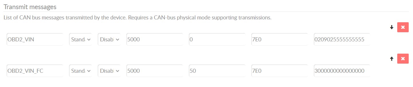
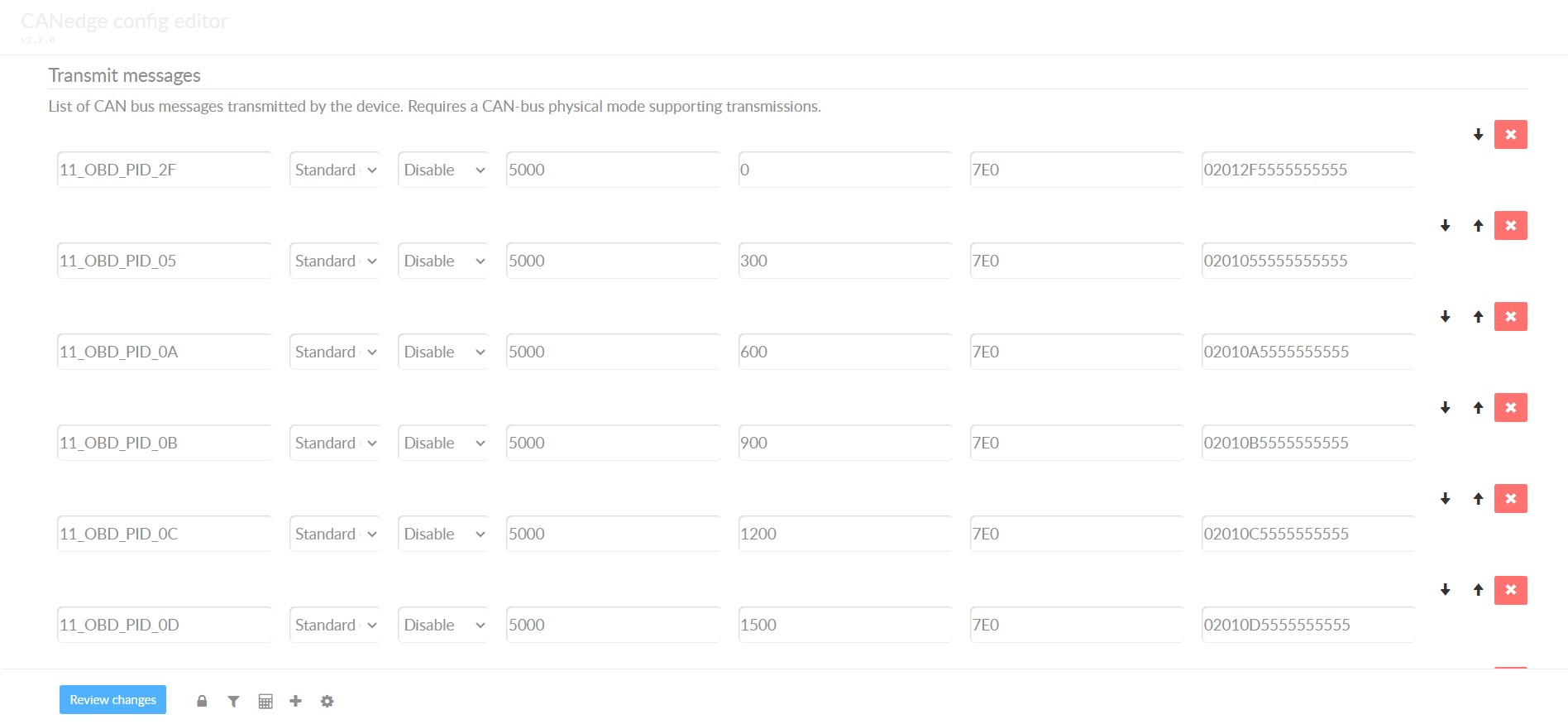 obd2-transmit-list-example-canedge An example list of CANedge OBD2 PID requests
 OBD2 data decoded visual plot asammdf CAN bus DBC file asammdf lets you DBC decode and visualize OBD2 data
#3: DBC Decode Raw OBD2 Data
The final step in the can obd2 data logging process is to decode the raw data into physical values that you can understand and analyze, such as kilometers per hour (km/h) or degrees Celsius (°C). This is where DBC (CAN database) files come into play.
The necessary decoding information for standard OBD2 PIDs is specified in ISO 15031-5/SAE J1979 and is also widely available in resources like Wikipedia. To simplify this process, we offer a free OBD2 DBC file. This DBC file is designed to be readily used with most CAN bus software tools, making it easy to DBC decode your raw can obd2 data.
Decoding OBD2 data is somewhat more complex than decoding standard CAN signals. This complexity arises because different OBD2 PIDs are transmitted using the same CAN ID (e.g., 0x7E8). Therefore, the CAN ID alone is not sufficient to uniquely identify the signals encoded in the payload.
To accurately decode can obd2 data, you need to consider not only the CAN ID but also the OBD2 mode and the specific OBD2 PID. This approach is a form of multiplexing known as ‘extended multiplexing‘. It allows multiple signals (different PIDs within the same mode) to be transmitted under the same CAN ID. This extended multiplexing can be effectively managed and implemented in software tools through the use of DBC files, which can define the decoding rules based on the CAN ID, mode, and PID combination.
CANedge: OBD2 Data Logger
The CANedge provides a streamlined solution for recording can obd2 data directly to an SD card (supporting 8-32 GB). Simply connect the CANedge to your vehicle’s OBD2 port to start logging. The recorded data can then be decoded and analyzed using free software and APIs, along with our OBD2 DBC file, making the entire process efficient and user-friendly.
OBD2 logger intro
CANedge
OBD2 Multi-Frame Examples [ISO-TP]
As mentioned earlier, all can obd2 data communication relies on the ISO-TP (transport protocol) as defined in ISO 15765-2. So far, most examples have focused on single-frame communication. This section will provide examples of multi-frame communication, which is necessary for transmitting larger OBD2 messages.
Multi-frame OBD2 communication involves the use of flow control frames to manage the data exchange (for more details, see our UDS introduction). In practice, for many OBD2 applications, this can be simplified by transmitting a static flow control frame approximately 50 milliseconds after the initial request frame. This approach is demonstrated in the CANedge configuration example shown below.
Furthermore, processing multi-frame OBD2 responses effectively requires CAN software and API tools that support ISO-TP, such as the CANedge MF4 decoders. These tools are designed to handle the complexities of multi-frame messages and ensure accurate data reconstruction for can obd2 analysis.
 OBD2-multi-frame-request-message-vehicle-identification-number
Example 1: OBD2 Vehicle Identification Number (VIN)
The Vehicle Identification Number (VIN) is often essential for telematics, diagnostics, and various vehicle-related applications. Retrieving the VIN using can obd2 involves multi-frame communication due to the length of the VIN. For a deeper understanding of VIN retrieval and its applications, you might find our introduction to UDS helpful.
To extract the VIN from a vehicle using OBD2 requests, you use Mode 0x09 (Vehicle Information) and PID 0x02 (Vehicle Identification Number):
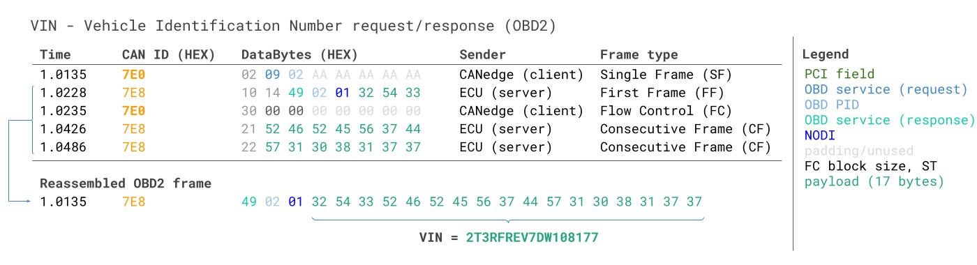 VIN Vehicle Identification Number OBD2 Example multi-frame
The diagnostic tool initiates the process by sending a Single Frame request. This request includes the PCI field (set to 0x02), the request service identifier (0x09 for Mode 0x09), and the PID (0x02 for VIN).
The vehicle responds with a First Frame, which contains the PCI, the total length of the multi-frame message (0x014, which is 20 bytes in decimal), the mode in the response format (0x49, indicating response to Mode 0x09), and the PID (0x02). Following the PID, the response includes the byte 0x01, representing the Number Of Data Items (NODI), which is 1 in this case, as we are requesting a single VIN. The subsequent 17 bytes contain the VIN itself, encoded in hexadecimal ASCII. These HEX values can be converted to standard ASCII characters to obtain the readable VIN, using methods detailed in our UDS introduction. This example showcases a typical multi-frame can obd2 exchange for retrieving vehicle-specific information.
Example 2: OBD2 Multi-PID Request (6x)
OBD2 standards allow diagnostic tools to request up to 6 Mode 0x01 OBD2 PIDs in a single request frame. When such a request is made, the ECU is expected to respond with data for all the supported PIDs from the requested set, omitting data for any unsupported PIDs. If necessary, the response may span multiple frames, adhering to ISO-TP for multi-frame communication. This capability aims to enhance the efficiency of can obd2 data retrieval by reducing the number of requests needed to gather multiple parameters.
This multi-PID request feature offers a way to collect can obd2 data at a potentially higher frequency and with greater efficiency. However, it also introduces complexities in data interpretation. The signal encoding in the response becomes specific to the method of request, which can complicate the use of generic OBD2 DBC files for decoding. For this reason, we generally do not recommend using multi-PID requests in practice, especially for data logging applications where standardized decoding is preferred. Below is an example trace illustrating what a multi-PID request and response might look like:
 Requesting multiple PIDs in one request
The multi-frame response structure in a multi-PID request scenario is similar to the VIN example, but with an added layer of complexity. The payload includes not only the requested PIDs but also the corresponding data for each of them. In practice, the PIDs in the response are often ordered in the same sequence as they were requested, as seen in the example. However, it’s important to note that the ISO 15031-5 standard does not strictly mandate this ordering.
Decoding these multi-PID responses using standard DBC files can be very challenging. Therefore, we advise against using this method for practical can obd2 data logging unless you are working with tools specifically designed to support multi-PID requests and their decoding. Effectively, you’re dealing with a complex case of extended multiplexing, compounded by multiple instances of it within a single payload. Furthermore, if you send multiple such multi-PID requests, distinguishing between the responses and correctly associating them with the original requests becomes even more difficult to manage solely through DBC file manipulations.
While it might be possible to work around these challenges with custom scripts and by also logging the transmit messages from your diagnostic tool, allowing the script to interpret responses based on the corresponding requests, such approaches are generally complex to scale and maintain.
Example 3: OBD2 Diagnostic Trouble Codes (DTCs)
OBD2 provides a service to request emissions-related Diagnostic Trouble Codes (DTCs) using Mode 0x03, known as ‘Show stored Diagnostic Trouble Codes’. When requesting DTCs, no PID is included in the request. The targeted ECU(s) will then respond with the number of DTCs currently stored in their memory (which could be zero if no DTCs are present) and the DTCs themselves, with each DTC typically occupying 2 data bytes. If more than two DTCs are stored, the response will require multiple frames, utilizing ISO-TP for transport. Retrieving DTCs is a fundamental aspect of can obd2 diagnostics.
The 2-byte DTC value is structured into two parts, as specified by ISO 15031-5 and ISO 15031-6. The first 2 bits of the first byte define the ‘category’ of the DTC (e.g., Powertrain, Chassis, Body, Network). The remaining 14 bits form a 4-digit code, usually displayed in hexadecimal format, as illustrated below. Decoded DTC values can be looked up in various OBD2 DTC lookup tools, such as repairpal.com, to get a textual description of the fault.
The example below illustrates a request to an ECU that has 6 DTCs stored. The multi-frame response will contain these DTCs, each encoded in 2 bytes, following the structure described. Understanding DTCs and how to retrieve them via can obd2 is crucial for vehicle diagnostics and repair.
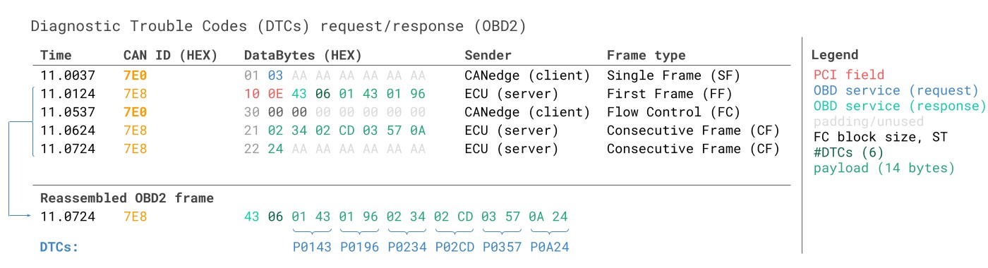 OBD2 Diagnostic Trouble Codes DTC CAN Bus Request Response Example
Can OBD2 Data Logging – Use Case Examples
OBD2 data logging from cars and light trucks has a wide array of practical applications across various industries. The ability to access and record vehicle data through can obd2 opens up possibilities for enhancing vehicle performance, maintenance, and management.
Logging data from cars
OBD2 data logging in cars can be instrumental in several areas, including:
- Fuel Cost Reduction: By analyzing parameters like fuel consumption, speed, and engine load, drivers and fleet managers can identify inefficient driving habits and optimize routes to reduce fuel costs.
- Driving Improvement: Data on driving behavior, such as acceleration, braking, and speed variations, can be used to provide feedback to drivers for improving driving safety and efficiency.
- Prototype Part Testing: Automotive engineers can use OBD2 data to monitor the performance and impact of prototype parts under real-world driving conditions, aiding in the development and validation process.
- Insurance: Insurance companies can utilize OBD2 data to assess driving risk, offer usage-based insurance policies, and potentially reduce premiums for safe driving.
obd2 logger
Real-time car diagnostics
OBD2 interfaces enable real-time streaming of vehicle data, which is invaluable for:
- Vehicle Issue Diagnosis: Mechanics and technicians can use real-time OBD2 data to diagnose vehicle problems more efficiently, monitoring live parameters to pinpoint faults.
- Performance Monitoring: Enthusiasts and professionals can monitor engine and vehicle performance in real-time, whether on the road or on a track, for tuning and analysis purposes.
obd2 streaming
Predictive maintenance
Integrating OBD2 data with IoT (Internet of Things) technologies allows for:
- Predictive Maintenance: By continuously monitoring OBD2 data in the cloud, potential vehicle breakdowns can be predicted and prevented, reducing downtime and maintenance costs.
- Fleet Management: Fleet operators can use OBD2 data for remote vehicle health monitoring, optimizing maintenance schedules, and improving overall fleet efficiency.
predictive maintenance
Vehicle blackbox logger
An OBD2 logger can function as a ‘black box’ for vehicles and equipment, providing crucial data for:
- Incident Analysis: In case of accidents or disputes, recorded OBD2 data can provide insights into vehicle behavior and conditions leading up to the event.
- Warranty and Diagnostics: For leased vehicles or equipment under warranty, OBD2 loggers can record operational data for diagnostic purposes and to verify usage conditions.
can bus blackbox
Do you have an OBD2 data logging use case? Reach out for free sparring!
Contact us
For more intros, see our guides section – or download the ‘Ultimate Guide’ PDF.
Need to log/stream OBD2 data?
Get your OBD2 data logger today!
Buy now
Contact us
Recommended for you
OBD2 DATA LOGGER: EASILY LOG & CONVERT OBD2 DATA
 CANedge2 – Dual CAN Bus Telematics Dongle
CANEDGE2 – PRO CAN IoT LOGGER
CAN BUS INTERFACE: STREAMING OBD2 DATA WITH SAVVYCAN