The fourth generation BMW 5 Series, known as the E39, was produced between 1996 and 2003 and is a favorite among BMW enthusiasts. If you own a 1998 BMW 5 Series and are looking to perform diagnostics or troubleshoot electrical issues, understanding your fuse box locations and fuse assignments is crucial, especially when it comes to the OBD2 system. This guide will provide you with comprehensive information about the fuse boxes in your 1998 BMW 5 Series (and models from 1996-2003), including fuse diagrams and layouts, to help you effectively maintain your vehicle.
This article covers various BMW 5 Series E39 models including the 520i, 520d, 523i, 525d, 525td, 525tds, 528i, 530i, 530d, 535i, and 540i. Let’s dive into the details to help you locate the specific fuse related to your OBD2 port or any other electrical component.
BMW 5 Series (E39) Fuse Box Locations and Diagrams (1996-2003)
The BMW E39 5 Series has multiple fuse box locations throughout the vehicle. Understanding where these are is the first step in diagnosing any electrical problem, including issues that might affect your OBD2 diagnostic port. The primary fuse box locations are:
- Engine Compartment: Under the hood, this box contains fuses and relays for critical engine and vehicle systems.
- Glove Compartment: Inside the cabin, behind the glove box, this location houses fuses for interior electronics and comfort features.
- Footwell: On the right side footwell, under the carpet, this area contains high-current fuses for major systems.
- Luggage Compartment (Trunk): In the trunk, on the right side, behind a cover, you’ll find fuse boxes related to rear vehicle functions and high-power components.
Let’s explore each location in detail.
Engine Compartment Fuse Box
The engine compartment fuse box is easily accessible and contains fuses and relays vital for the engine’s operation.
Fuse Box Location
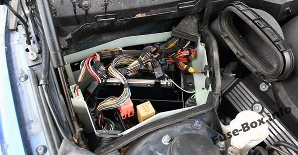 Engine compartment fuse box location in a BMW 5-Series (E39, 1996-2003)
The fuse box in the engine compartment is typically located on the passenger side of the engine bay. Refer to your owner’s manual for the exact location if needed.
Diagram (Type 1)
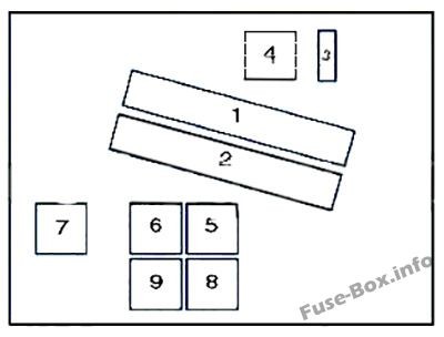 Engine compartment fuse box diagram type 1 for BMW 5-Series (E39, 1996-2003)
Here’s a fuse assignment table for engine compartment fuse box (Type 1):
| # | Component |
|---|---|
| 1 | Engine control module |
| 2 | Transmission control module |
| 3 | Engine control module fuse |
| 4 | Engine control module relay |
| 5 | Windscreen wiper motor relay I |
| 6 | Windscreen wiper motor relay II |
| 7 | Air conditioning condenser blower motor relay I |
| 8 | Air conditioning condenser blower motor relay III |
| 9 | ABS relay |
Diagram (Type 2)
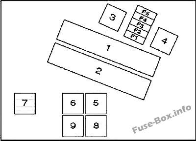 Engine compartment fuse box diagram type 2 for BMW 5-Series (E39, 1996-2003)
Here’s a fuse assignment table for engine compartment fuse box (Type 2), which is more detailed:
| # | A | Component |
|---|---|---|
| 1 | Engine control module (ECM) | |
| 2 | Transmission control module (TCM) | |
| 3 | Engine control (EC) relay | |
| 4 | Ignition coil relay – except 520i (22 6S 1)/525i/530i | |
| 5 | Windscreen wiper motor relay 1 | |
| 6 | Windscreen wiper motor relay 2 | |
| 7 | AC condenser blower motor relay 1 (until 03/98) | |
| 8 | AC condenser blower motor relay 3 (until 03/98) | |
| 9 | Secondary air injection (AIR) pump relay | |
| F1 | 30A | Engine control module (ECM), evaporative emission (EVAP) canister purge valve, mass airflow (MAF) sensor, camshaft position (CMP) sensor 1, engine coolant thermostat – 535i/540i |
| F2 | 30A | Secondary air injection (AIR) pump, intake manifold air control solenoid, injectors (except 520i (22 6S1)/525i/530i), engine control module (ECM), evaporative emission (EVAP) canister purge valve, camshaft position (CMP) actuator 1 & 2, idle speed control (ISC) actuator |
| F3 | 20A | Crankshaft position (CKP) sensor, camshaft position (CMP) sensor 1 & 2, mass airflow (MAF) sensor |
| F4 | 30A | Heated oxygen sensors (H02S), transmission control module (TCM) |
| F5 | 30A | Ignition coil relay – except 520i (22 6S1)/525i/530i |
Glove Compartment Fuse Box
The fuse box in the glove compartment is a central location for many of the car’s interior electrical circuits.
Fuse Box Location
To access the glove compartment fuse box, you need to open the glove compartment and release it from its latches.
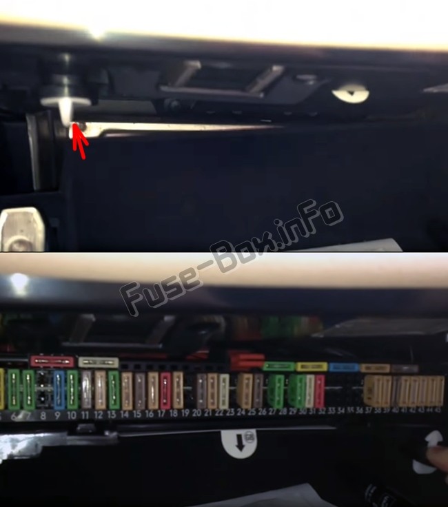 Glove compartment fuse box location in a BMW 5-Series (E39, 1996-2003)
Open the glove compartment, turn the two clamps to the left, and pull the panel down to access the fuses.
Fuse Box Diagram
Remember that fuse layouts can vary, and your vehicle’s specific fuse allocation scheme will be located on a diagram usually found under the fuse box cover.
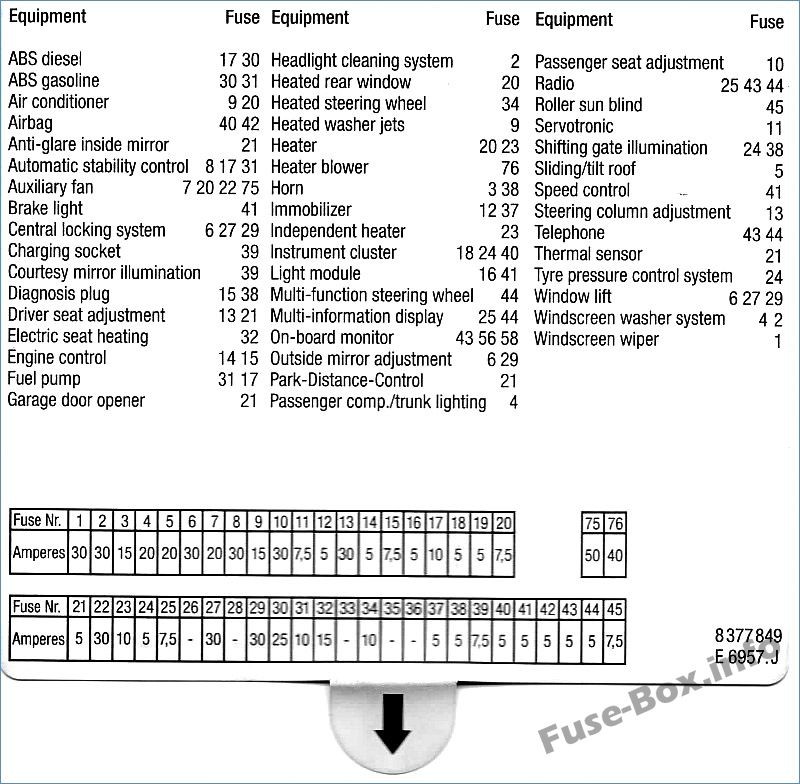 Glove compartment fuse box diagram for BMW 5-Series (E39, 1996-2003)
Here are the fuse assignments for the glove compartment fuse box for models until 03.1998:
| # | A | Component |
|---|---|---|
| F1 | 30A | Windscreen wiper motor relay |
| F2 | 30A | Headlamp washers |
| F3 | 15A | Horn |
| F4 | 20A | Multifunction control module |
| F5 | 20A/30A | Sunroof |
| F6 | 30A | Electric door mirror, passenger’s side |
| F7 | 20A/30A | AC condenser blower motor relay 1 |
| F8 | – | – |
| F9 | 15A | AC/ heater control module |
| F10 | 30A | Seat adjustment – passenger’s side |
| F11 | 7.5A | Multifunction control module – variable power steering |
| F12 | 5A | Immobilizer |
| F13 | 30A | Seat adjustment – driver’s side, steering column adjustment |
| F14 | 5A | Engine control module (ECM) |
| F15 | 7.5A | Transmission control module (TCM), engine oil level sensor, alternator, electrics box temperature switch (530d) |
| F16 | 5A | Lamps control module |
| F17 | 10A | Fuel pump relay, ABS control module, multi switch assembly |
| F18 | 5A | Instrument panel |
| F19 | 5A | Overvoltage protection relay 2 |
| F20 | 5A/7.5A | AC/heater control module, heated rear window relay, tyre pressure monitor control module |
| F21 | 5A | Cigarette lighter relay, seat adjustment relay/steering column adjustment relay, garage door opener, parking aid control module, anti-dazzle interior mirror |
| F22 | 30A | AC condenser blower motor relay 2 |
| F23 | 7.5A | Digital multifunction display – rear |
| F24 | 5A | Instrument panel, tyre pressure monitor control module, steering position sensor |
| F25 | 7.5A | Digital multifunction display |
| F26 | – | – |
| F27 | 30A | Multifunction control module |
| F28 | 15A | Automatic transmission (AT) |
| F29 | 30A | Door function control module, driver’s side |
| F30 | 25A | ABS control module |
| F31 | 10A | Fuel pump relay, ABS control module, secondary air injection (AIR) pump relay (petrol) |
| F32 | 25A | Multi switch assembly |
| F33 | – | – |
| F34 | 10A | Multifunction steering wheel/airbag assembly, heated steering wheel |
| F35 | 5A | AC condenser blower motor, rear |
| F36 | – | – |
| F37 | 5A | Immobilizer control module |
| F38 | 5A | Multifunction control module, horn relay, rain sensor, transmission shift hold switch (AT), data link connector (DLC) |
| F39 | 7.5A | Vanity mirror lamps, rechargeable torch |
| F40 | 5A | Instrument panel, seat adjustment control module, airbag crash sensor, seat belt contact switch (drivers side) |
| F41 | 5A | Lamps control module, clutch pedal position (CPP) switch, brake pedal position (BPP) switch |
| F42 | 5A | SRS control module |
| F43 | 5A | Over voltage protection relay 1 |
| F44 | 5A | Multifunction steering wheel/airbag assembly, steering wheel, digital multifunction display – front/rear |
| F45 | 7.5A | Multi switch assembly |
Here are the fuse assignments for the glove compartment fuse box for models since 03.1998, which is relevant for the 1998 BMW 5 Series:
| # | A | Component |
|---|---|---|
| F1 | 30A | Windscreen wiper motor relay |
| F2 | 30A | Headlamp washers |
| F3 | 15A | Horn |
| F4 | 20A | Multifunction control module |
| F5 | 20A/30A | Sunroof |
| F6 | 30A | Electric door mirror, passenger’s side |
| F7 | 20A/30A | Cigarette lighter – front (09/00) |
| F8 | – | – |
| F9 | 15A | AC/heater control module |
| F10 | 30A | Seat adjustment – passenger’s side |
| F11 | 7.5A | Multifunction control module – variable power steering |
| F12 | 5A | Immobilizer |
| F13 | 30A | Seat adjustment – driver’s side, steering column adjustment |
| F14 | 5A | Engine control module (ECM) |
| F15 | 7.5A | Transmission control module (TCM), engine oil level sensor, alternator, electrics box temperature switch (530d) |
| F16 | 5A | Lamps control module |
| F17 | 10A | Fuel pump relay, ABS control module, multi switch assembly |
| F18 | 5A | Instrument panel |
| F19 | 5A | Overvoltage protection relay 2 |
| F20 | 5A/7.5A | AC/heater control module, heated rear window relay, tyre pressure monitor control module |
| F21 | 5A | Cigarette lighter relay, seat adjustment relay/steering column adjustment relay, garage door opener, parking aid control module, anti-dazzle interior mirror |
| F22 | 25A | Fuel pump relay – 530d/520i(226S1)/525i/530i |
| F23 | 7.5A | Digital multifunction display – rear |
| F24 | 5A | Instrument panel, tyre pressure monitor control module, steering position sensor |
| F25 | 7.5A | Digital multifunction display |
| F26 | – | – |
| F27 | 30A | Multifunction control module |
| F28 | 15A | Automatic transmission (AT) |
| F29 | 30A | Door function control module, driver’s side |
| F30 | 25A | ABS control module |
| F31 | 10A | Fuel pump relay, ABS control module, secondary air injection (AIR) pump relay (petrol) |
| F32 | 25A | Multi switch assembly |
| F33 | – | – |
| F34 | 10A | Multifunction steering wheel/air bag assembly, heated steering wheel |
| F35 | 5A | AC condenser blower motor, rear |
| F36 | – | – |
| F37 | 5A | Immobilizer control module |
| F38 | 5A | Multifunction control module, horn relay, rain sensor, transmission shift hold switch (AT), data link connector (DLC) |
| F39 | 7.5A | Vanity mirror lamps, rechargeable torch |
| F40 | 5A | Instrument panel, seat adjustment control module, airbag crash sensor, seat belt contact switch (driver’s side) |
| F41 | 5A | Lamps control module, clutch pedal position (CPP) switch, brake pedal position (BPP) switch |
| F42 | 5A | SRS control module |
| F43 | 5A | Overvoltage protection relay 1 |
| F44 | 5A | Multifunction steering wheel/air bag assembly, steering wheel, digital multifunction display – front/rear |
| F45 | 7.5A | Multi switch assembly |
While none of these fuses are directly labeled “OBD2 fuse,” fuse F38 (5A) in the glove compartment (since 03.1998) is associated with the “data link connector (DLC),” which is another term for the OBD2 port. If you’re experiencing issues with your OBD2 port not powering up or communicating, checking fuse F38 would be a good starting point.
Relay Block in the Glove Compartment
Behind the glove compartment fuse box, there is a relay block. Relays are switches that control higher current circuits.
Location
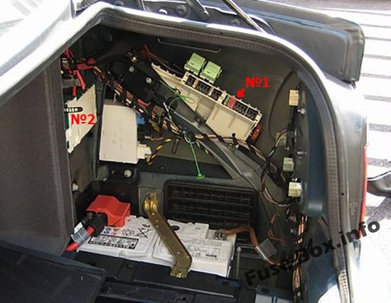
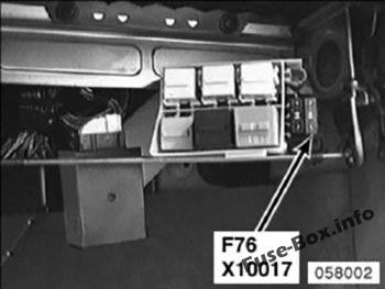 Relay block location behind the glove box fuse box in a BMW 5-Series (E39, 1996-2003)
The relay block is situated directly behind the fuse box in the glove compartment.
Diagram
Here’s a table detailing the relay assignments in this block:
| # | Component |
|---|---|
| 1 | AC condenser blower motor relay 2 (until 03/98) |
| 2 | Headlamp washer pump relay |
| 3 | – |
| 4 | Starter motor relay |
| 5 | Seat adjustment relay/steering column adjustment relay |
| 6 | Heater blower relay |
| F75 | (50A) AC condenser blower motor/engine coolant blower motor |
| F76 | (40A) AC/heater blower control module |
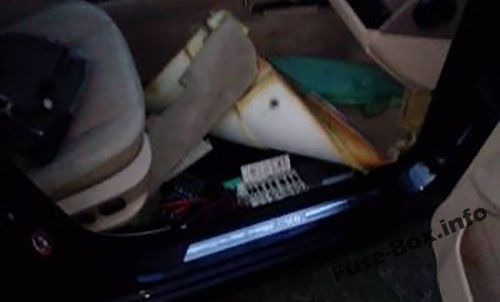
Block in the Footwell
The footwell block is located on the passenger side of the car, under the floor lining.
Location
 Footwell block location in a BMW 5-Series (E39, 1996-2003)
Located on the floor under the lining, on the right side of the car.
Diagram and Assignments
 Footwell block diagram 1 for BMW 5-Series (E39, 1996-2003)
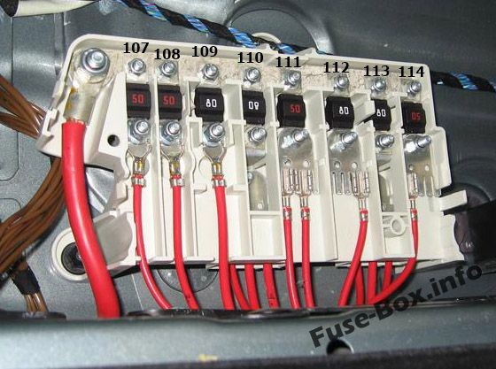 Footwell block diagram 2 for BMW 5-Series (E39, 1996-2003)
Here are the fuse assignments for the footwell block:
| # | A | Component |
|---|---|---|
| F107 | 50A | Secondary air injection (AIR) pump relay |
| F108 | 50A | ABS control module |
| F109 | 80A | Engine control (EC) relay, fuse box-engine bay (F4 & F5) |
| F110 | 80A | Fuse box-fascia 1 (F1-F12 & F22-F25) |
| F111 | 50A | Ignition switch |
| F112 | 80A | Lamps control module |
| F113 | 80A | Seat adjustment relay/steering column adjustment relay, fuse box-fascia 1 (F27-F30), fuse box-fascia 2 (F76), lamps control module, fuse box-fascia 1 (F13) – with lumbar support |
| F114 | 50A | Ignition switch, data link connector (DLC) |
Interestingly, fuse F114 (50A) in the footwell block is also listed with “data link connector (DLC).” This suggests that there might be multiple fuses that could indirectly affect the OBD2 port’s functionality, or this could be a higher current supply fuse for systems including the DLC.
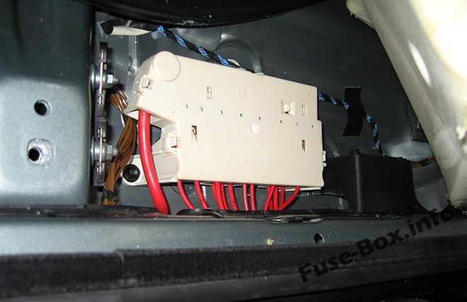
Fuse Boxes in the Luggage Compartment
The luggage compartment (trunk) houses additional fuse boxes, primarily on the right side.
Fuse Box Location
 Luggage compartment fuse box location in a BMW 5-Series (E39, 1996-2003)
Located on the right side, behind the cover in the trunk.
Box 1 Diagram
Fuse layouts in the trunk can also vary. Always check the diagram on the fuse box cover in your vehicle.
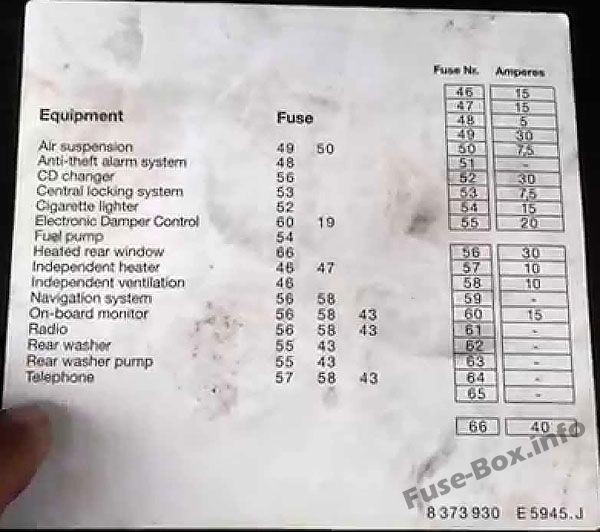 Luggage compartment fuse box 1 diagram for BMW 5-Series (E39, 1996-2003)
Here are the fuse and relay assignments for luggage compartment fuse box 1 (Type 1):
| # | A | Component |
|---|---|---|
| 1 | Overvoltage protection relay 1 | |
| 2 | Fuel pump relay | |
| 3 | Heated rear window relay | |
| 4 | Overvoltage protection relay 2 | |
| 5 | Fuel filler flap relay | |
| F46 | – | – |
| F47 | 15A/20A | Auxiliary heater |
| F48 | 5A | Anti-dazzle interior mirror, alarm system in-car movement control module, alarm system gradient sensor, alarm system horn |
| F49 | 30A | Suspension compressor relay |
| F50 | 7.5A | Suspension control module (with air suspension) |
| F51 | 30A | Cigarette lighter – rear |
| F52 | 30A | Cigarette lighter relay, cigarette lighter – front |
| F53 | 5A | Aerial signal amplifier, boot lid/tail gate lockstitch |
| F54 | 15A | Fuel pump relay |
| F55 | 20A | Rear screen wash/wipe relay |
| F56 | 30A | Audio unit, navigation system control module, audio unit output amplifier, audio unit CD changer, in-car monitor |
| F57 | 10A | Telephone |
| F58 | 10A | Overvoltage protection relay 1 |
| F59 | 20A | Trailer socket |
| F60 | 15A | Suspension control module, multi switch assembly |
| F61 | 25A | Rear seat heater switch, left, rear seat heater switch, right |
| F62 | – | – |
| F63 | – | – |
| F64 | – | – |
| F65 | – | – |
| F66 | 40A | Heated rear window relay |
| F67 | – | – |
Here are the fuse and relay assignments for luggage compartment fuse box 1 (Type 2):
| # | A | Component |
|---|---|---|
| 1 | Ignition main circuits relay | |
| 2 | Fuel pump relay | |
| 3 | Heated rear window relay | |
| 4 | Ignition auxiliary circuits relay | |
| 5 | Independent heater relay | |
| F46 | 15A | Independent heater/ventilation |
| F47 | 15A | Independent heater |
| F48 | 5A | Alarm system |
| F49 | 30A | Air suspension system |
| F50 | 7.5A | Air suspension system |
| F51 | – | – |
| F52 | 30A | Cigarette lighter |
| F53 | 7.5A | Central locking system |
| F54 | 15A | Fuel pump |
| F55 | – | – |
| F56 | 30A | Audio system, navigation system, on-board monitor |
| F57 | 10A | Cellular phone |
| F58 | 10A | Audio unit, on-board monitor, navigation system, telephone |
| F59 | – | – |
| F60 | 15A | Suspension adjustment control |
| F61 | – | – |
| F62 | – | – |
| F63 | – | – |
| F64 | – | – |
| F65 | – | – |
| F66 | 40A | Heated rear window |
| F67 | – | – |
| F6S | – | – |
| F69 | – | – |
| F70 | – | – |
| F71 | – | – |
| F72 | – | – |
| F73 | – | – |
| F74 | – | – |
Box 2 Diagram
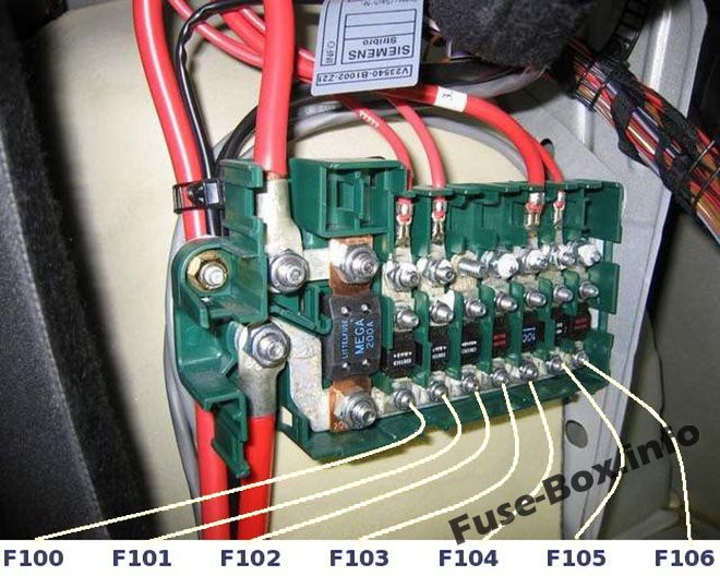 Luggage compartment fuse box 2 diagram for BMW 5-Series (E39, 1996-2003)
Here are the fuse assignments for luggage compartment fuse box 2:
| # | A | Component |
|---|---|---|
| F100 | 200A | Fuse box – footwell (F107-F114) |
| F101 | 80A | Fuse box – load area 1 (F46-F50, F66) |
| F102 | 80A | Fuse box – load area 1 (F51-F55) |
| F103 | 50A | Trailer control module |
| F104 | 50A | Overvoltage protection relay 2 |
| F105 | 100A | Fuse box – fascia 2 (F75), auxiliary heater |
| F106 | 80A | Fuse box – load area 1 (F56-F59) |
Conclusion
Understanding the fuse box layout for your 1998 BMW 5 Series is essential for diagnosing and resolving electrical issues, including problems related to your OBD2 port. While there isn’t a fuse explicitly labeled “OBD2 fuse,” checking fuses F38 in the glove compartment and F114 in the footwell, both associated with the Data Link Connector (DLC), is a crucial first step if you’re experiencing OBD2 communication problems. By using these diagrams and fuse assignments, you can efficiently troubleshoot and maintain your BMW E39, ensuring its longevity and performance. Always refer to your vehicle’s specific fuse diagram, usually located on the fuse box cover, for the most accurate information.
For further reading:
- How to check fuses in your car
- Step-by-step guide to replacing a blown fuse
- Common reasons for car fuses blowing
- Different types of automotive fuses explained