Are you struggling to connect your older vehicle’s 12 pin OBD1 system to modern diagnostic tools that use the 16 pin OBD2 standard? Many car enthusiasts and DIY mechanics face this challenge when working with classic cars. While pre-made adapter cables are available, building your own 12 Pin Obd1 To 16 Pin Obd2 adapter cable can be a cost-effective and rewarding project, especially if you possess basic soldering skills. This guide will walk you through creating your own OBD1 cable for less than $20, enabling you to use PC-based scan tools for vehicle diagnostics.
Before diving in, it’s worth noting that while this guide focuses on a DIY approach, there are readily available, user-friendly solutions that might be even simpler and cheaper. However, for those who enjoy hands-on projects and understanding the inner workings of automotive technology, building your own adapter offers a great learning experience.
To embark on this project, you will need a few key components and tools:
-
USB-to-Serial Port Adapter: A crucial component is a USB-to-SerialPort adapter. It’s vital to choose one based on an FTDI chip, like the Sabrent CB-FT1K or equivalent. Adapters using Prolific chips are not compatible with this cable setup. FTDI-based adapters ensure reliable communication. You can typically find these for around $20, and sometimes even as low as $10 if you shop around online.
-
Electronic Components: You’ll need a few basic electronic parts, easily sourced from electronics supply stores or online retailers:
- A 1K ohm resistor
- A diode (silicon or switching diode is suitable, avoid Zener diodes)
- A DB9 connector (9-pin female/socket type with solder terminals)
- Two pieces of insulated wire, each at least 6 inches long (AWG 20 or 22 stranded wire is recommended)
- While optional for initial testing, an OBD-1 12-pin plug would provide a more professional and robust connection to your vehicle’s diagnostic port.
-
USB Extension Cable (Optional): If your chosen USB adapter doesn’t come with a built-in cable, a USB extension cable will be necessary to provide extra length and flexibility.
-
Tools:
- Soldering iron and solder
- Wire stripper
Step 1: Constructing the OBD1 Cable
The first step is to physically assemble the cable. Refer to the diagram below for the wiring configuration. You can customize the wire lengths to your preference. Ensure proper insulation of the wires and components at the DB9 connector to prevent short circuits. It’s recommended to “tin” the wire ends that will connect to the OBD-1 connector with solder. This will keep the wire strands together, making connection easier and preventing fraying. Pay close attention to the diode’s polarity; the cathode (marked with a black band) must face towards the DB9 connector. Resistors, on the other hand, are not polarized and can be connected in either direction.
[  DIY OBD1 cable wiring diagram showing components like DB9 connector, resistor, and diode for connecting 12 pin OBD1 to PC via USB adapter ]
Step 2: Reprogramming the FTDI Chip
After wiring the cable, the next crucial step is to reprogram the FTDI chip within the USB-to-Serial Port adapter. For this OBD1 application, the TXD and RXD pin signals need to be inverted to ensure correct communication. To do this, you will need to download the FTDI utility program called “FT_Prog” directly from the official FTDI website.
[ 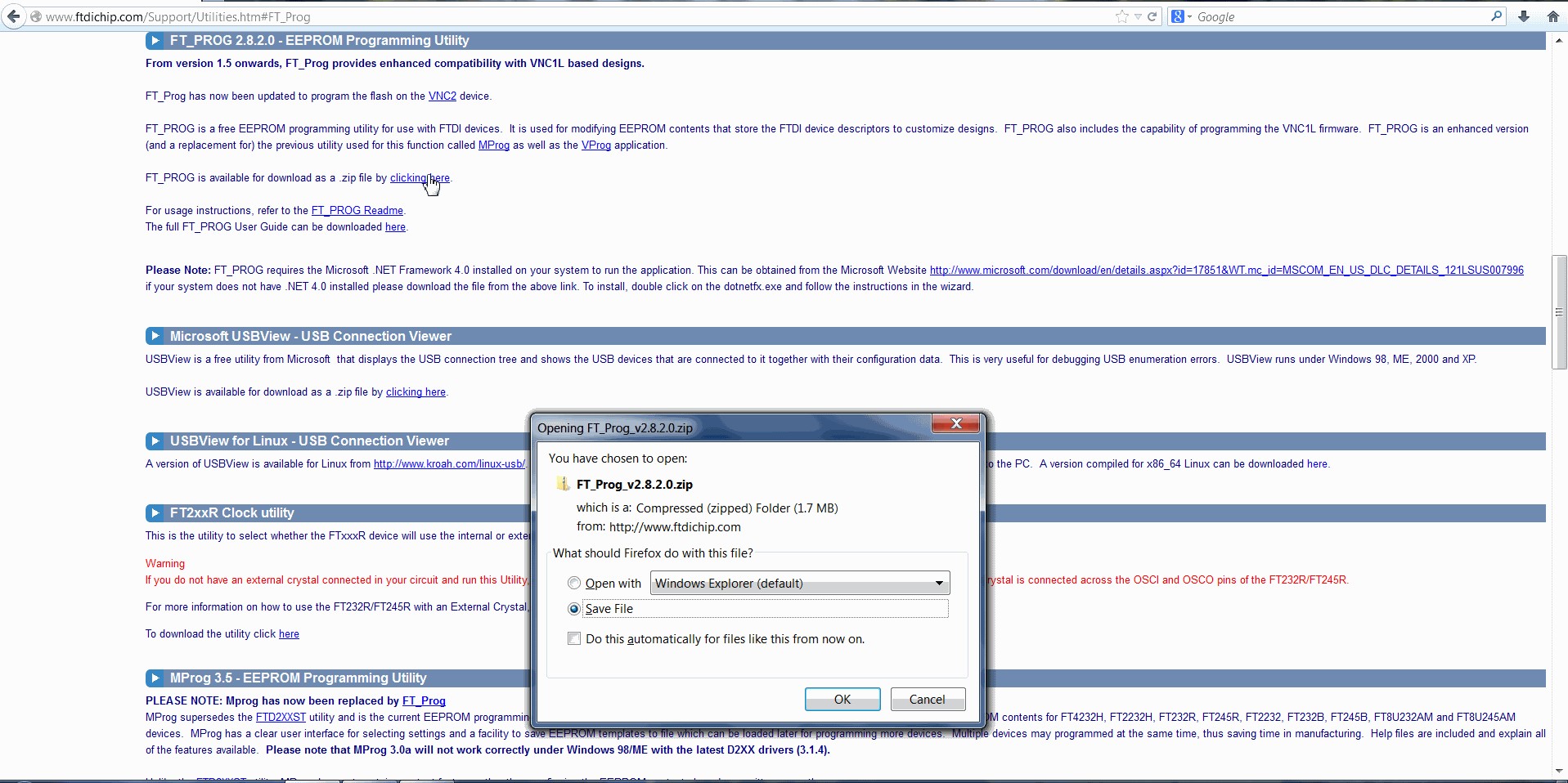 FT_Prog utility download page screenshot for reprogramming FTDI USB to serial adapter for OBD1 communication. ]
Install and launch FT_Prog. Connect your USB adapter cable to a USB port on your computer. Press the F5 key in FT_Prog to refresh the device list. Your adapter should appear in the left-hand device list box. If multiple devices are listed, disconnect any other USB-to-Serial adapters temporarily. If no devices are detected, double-check the driver installation for your USB adapter.
Once your device is recognized, navigate to “Hardware Specific” and then “Invert RS232 Signals”. Initially, none of the checkboxes should be selected. You need to check (turn ON) both “Invert TXD” and “Invert RXD” checkboxes as shown in the image below. This signal inversion is essential for proper communication with the OBD1 system.
[ 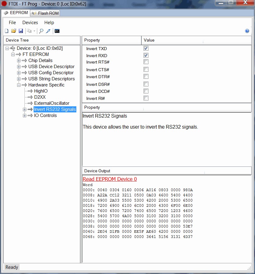 FT_Prog software interface showing 'Invert TXD' and 'Invert RXD' settings to enable OBD1 communication via USB adapter. ]
With the checkboxes correctly set, program the adapter by pressing “Ctrl” + “P” keys together, or by selecting “Devices” then “Program” from the menu. A “Program Devices” window will appear. Click the “Program” button and wait for the “Finished Programming” message to appear at the bottom left of the window.
[ 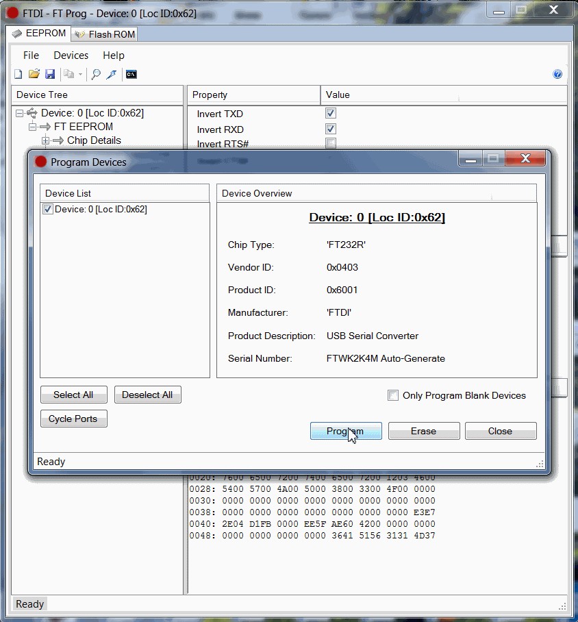 FT_Prog program device dialog box confirming successful reprogramming of FTDI adapter for OBD1 cable functionality. ]
Close all FT_Prog windows and exit the program. Should you wish to revert the adapter to its original settings for other applications, simply repeat these steps but uncheck the “Invert TXD” and “Invert RXD” boxes.
Conclusion
Your DIY 12 pin OBD1 to 16 pin OBD2 adapter cable is now complete. Connect your newly তৈরি cable to your vehicle’s OBD1 port and the USB adapter to your computer. Install and run your chosen OBD1 compatible scan tool software. The black wire from the diagram typically connects to pin A on the OBD-1 connector, and the white wire to pin M.
Important Note: Shorting the black and white wires accidentally will not cause damage, but it will interrupt communication with the vehicle’s Powertrain Control Module (PCM) while shorted. This cable configuration is primarily designed for 4th generation vehicles. Earlier OBD1 systems might require a different resistor value and connection to a different pin on the OBD1 connector. Always consult your vehicle’s service manual or specific OBD1 documentation for precise compatibility and wiring information.