Need a deep dive into Obd2 Protocols?
This comprehensive guide provides an in-depth exploration of On-Board Diagnostics (OBD2) protocols, covering everything from the OBD2 connector and Parameter IDs (PIDs) to the intricacies of the CAN bus integration. Going beyond a basic introduction, we’ll equip you with the knowledge to understand, request, and decode OBD2 data effectively. Discover key logging applications and gain practical tips that elevate this resource to your #1 OBD2 protocol tutorial.
You can also enhance your understanding by watching our OBD2 intro video above – or for a portable reference, download our comprehensive PDF guide.
What are OBD2 Protocols?
OBD2 protocols form the backbone of your vehicle’s self-diagnostic system. They represent a standardized set of rules and communication methods that enable the extraction of crucial diagnostic trouble codes (DTCs) and real-time operational data through the OBD2 connector. This standardization is key, making vehicle diagnostics accessible and consistent across different manufacturers.
You’ve likely already interacted with the OBD2 system indirectly. Consider the malfunction indicator light illuminating on your dashboard—this is your vehicle signaling a potential issue detected by the OBD2 system.
When you take your car to a mechanic, they utilize an OBD2 scanner to pinpoint the problem. This process involves connecting the OBD2 reader to the standardized OBD2 16 pin connector, typically located near the steering wheel. The scanner then sends ‘OBD2 requests’ to the vehicle’s onboard computer system. In response, the car transmits ‘OBD2 responses,’ which may contain vital information such as speed readings, fuel levels, or those critical Diagnostic Trouble Codes (DTCs). This standardized communication drastically accelerates the troubleshooting process, saving time and resources.
Illustration of an OBD2 scanner being used to diagnose a car, highlighting the malfunction indicator light (MIL) or check engine light.
OBD2 Connector Overview
The OBD2 connector is the physical interface point for accessing your vehicle’s diagnostic data. This standardized 16-pin Data Link Connector (DLC) ensures compatibility across a wide range of vehicles, allowing diagnostic tools to communicate effectively with the car’s computer system.
Malfunction Indicator Light (MIL)
The Malfunction Indicator Light (MIL), often referred to as the check engine light, is a key indicator of OBD2 system activity. When the MIL illuminates, it signals that the OBD2 system has detected an issue related to emissions or other vehicle systems, prompting further investigation using an OBD2 scanner.
History and Evolution of OBD2 Protocols
The genesis of OBD2 protocols can be traced back to California, where the California Air Resources Board (CARB) mandated On-Board Diagnostics in all new vehicles starting from 1991. This initial requirement was primarily focused on enhancing emission control and monitoring.
The Society of Automotive Engineers (SAE) played a crucial role in formalizing these early OBD systems into the OBD2 standard. They standardized Diagnostic Trouble Codes (DTCs) and the physical OBD connector itself through the SAE J1962 specification, ensuring uniformity across different vehicle manufacturers.
From this foundation, the adoption of the OBD2 standard expanded progressively:
- 1996: OBD2 compliance became mandatory in the USA for all cars and light trucks.
- 2001: The European Union mandated OBD2 for gasoline cars.
- 2003: The EU extended the mandate to include diesel cars (EOBD – European On-Board Diagnostics).
- 2005: OBD2 requirements in the US broadened to encompass medium-duty vehicles.
- 2008: A significant shift occurred as US vehicles were required to adopt ISO 15765-4 (CAN) as the underlying protocol for OBD2 communication.
- 2010: Finally, OBD2 compliance became mandatory in the US for heavy-duty vehicles, completing the phased rollout across vehicle categories.
Infographic illustrating the history of OBD2 development and its connection to emission control and CAN bus technology.
Timeline visualization of key milestones in OBD2 history, from its origins to widespread adoption.
Conceptual image representing the future of OBD, potentially including OBD3 with remote diagnostics and cloud connectivity.
OBD2 Timeline
| Year | Milestone | Region/Vehicle Type |
|---|---|---|
| 1991 | CARB mandates OBD in new cars | California |
| 1996 | OBD2 mandatory | USA – Cars/Light Trucks |
| 2001 | OBD2 mandatory | EU – Gasoline Cars |
| 2003 | EOBD (OBD2 for Diesel) mandatory | EU – Diesel Cars |
| 2005 | OBD2 mandatory | USA – Medium Duty Vehicles |
| 2008 | ISO 15765-4 (CAN) mandatory for OBD2 | USA – All Cars |
| 2010 | OBD2 mandatory | USA – Heavy Duty Vehicles |
The Future of OBD2: Trends and Innovations
While OBD2 remains a cornerstone of vehicle diagnostics, its future is evolving, particularly in response to new vehicle technologies and connectivity demands.
Originally conceived for stationary emission testing, legislated OBD2 has primarily focused on emission control. This has led to an interesting situation with electric vehicles (EVs). Currently, electric vehicles are not legally obligated to support OBD2 in any standard form. This is reflected in the automotive industry, as most modern EVs do not implement standard OBD2 requests. Instead, many manufacturers opt for OEM-specific UDS (Unified Diagnostic Services) communication protocols. This shift often makes accessing and interpreting data from EVs challenging, except in cases where the proprietary communication rules have been reverse-engineered. Examples of successful reverse engineering efforts include projects focused on Tesla, Hyundai/Kia, Nissan and VW/Skoda EVs.
Recognizing the limitations of current OBD2 implementations, especially in terms of data richness and reliance on older lower-layer protocols, the automotive industry has been developing modern alternatives. WWH-OBD (World-Wide Harmonized OBD) and OBDonUDS (OBD on UDS) are prominent examples. These next-generation protocols aim to enhance and streamline OBD communication by utilizing the more advanced UDS protocol as a foundation. For a deeper understanding of UDS, refer to our comprehensive introduction to UDS.
In an increasingly connected world, traditional OBD2 testing methods appear somewhat outdated. Manual emission control checks are not only time-consuming but also costly.
The proposed solution to modernize and enhance OBD capabilities is OBD3 – the integration of telematics into all vehicles.
OBD3 envisions embedding a small radio transponder in every car, similar to those used for bridge tolls. This technology would enable vehicles to wirelessly transmit their vehicle identification number (VIN) and DTCs via WiFi to a central server for automated diagnostics and monitoring.
Many devices today already facilitate the wireless transmission of CAN or OBD2 data using WiFi or cellular networks. Examples include the CANedge2 WiFi CAN logger and the CANedge3 3G/4G CAN logger.
While OBD3 offers benefits in terms of cost savings and convenience, it also presents political and social challenges, primarily concerning surveillance and data privacy.
Challenges and Controversies
The OBD2 protocol, initially intended for stationary emission controls, has expanded its role significantly. Today, it’s extensively used by third-party services to generate real-time vehicle data, facilitated by OBD2 dongles, CAN loggers and similar devices. However, this expanded use has drawn concerns from the German car industry, which is seeking to limit third-party access to OBD2 data.
As Christoph Grote, SVP Electronics at BMW, stated in 2017: “OBD has been designed to service cars in repair shops. In no way has it been intended to allow third parties to build a form of data-driven economy on the access through this interface“.
The industry proposal involves “turning off” OBD2 functionality during normal driving, centralizing data collection within manufacturer-controlled servers. This approach would effectively place automotive manufacturers in control of the burgeoning ‘automotive big data’ domain.
The rationale behind this move is often framed around security concerns, such as mitigating the risk of car hacking. However, many industry observers view it as a commercially motivated strategy. Whether this trend gains momentum remains to be seen, but it has the potential to significantly disrupt the market for third-party OBD2-based services.
Visual representation of the potential future trend where electric vehicles might limit or remove access to OBD2 data.
Enhance Your Expertise with Our ‘Ultimate CAN Guide’
Eager to become a CAN bus expert?
Access our comprehensive collection of 12 ‘simple intros’ compiled into a single, 160+ page PDF resource:
Download now
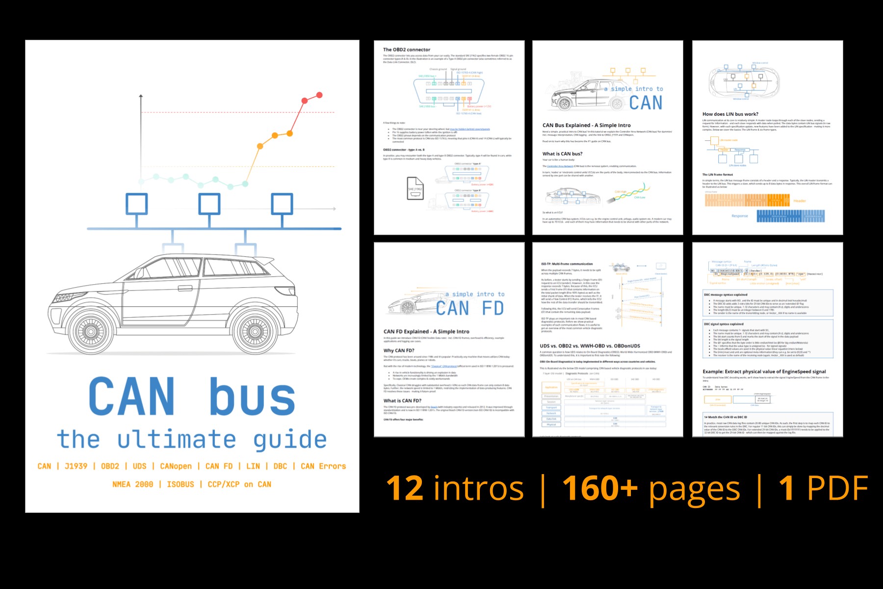 CAN Bus – The Ultimate Guide Tutorial PDF
OBD2 Standards and Protocols in Detail
On-board diagnostics, specifically OBD2, operates as a higher-layer protocol, similar to a language used for communication. In contrast, CAN (Controller Area Network) bus functions as the communication medium, analogous to a telephone line. This hierarchical structure places OBD2 alongside other CAN-based higher-layer protocols such as J1939, CANopen, and NMEA 2000.
The OBD2 standards comprehensively define various aspects, including the OBD2 connector specifications, lower-layer communication protocols, OBD2 Parameter IDs (PIDs), and more.
These standards can be effectively visualized using the 7-layer OSI model, which helps to categorize the different aspects of OBD2 communication. The following sections will delve into the most critical standards.
Within the OSI model framework, it’s notable that both SAE (Society of Automotive Engineers) and ISO (International Organization for Standardization) standards cover multiple layers. This dual representation reflects the historical development of OBD standards in the USA (SAE) and Europe (ISO). Many of these standards are technically very similar, for instance, SAE J1979 is largely equivalent to ISO 15031-5, and SAE J1962 closely mirrors ISO 15031-3.
Diagram illustrating the relationship between OBD2, CAN bus, and the OSI 7-layer model, highlighting relevant ISO and SAE standards.
Detailed pinout diagram of a Type A OBD2 connector socket (female), also known as a Data Link Connector (DLC).
OBD2 Connector Standard (SAE J1962)
The OBD2 connector, a 16-pin interface, is designed for easy access to vehicle data and is meticulously specified by the SAE J1962 standard (and its ISO counterpart, ISO 15031-3).
The illustration above shows a typical Type A OBD2 pin connector, also known as a Data Link Connector (DLC).
Key points regarding the OBD2 connector include:
- It is generally located in the vicinity of the steering wheel, although its exact position may be concealed depending on the vehicle model.
- Pin 16 consistently provides battery power, often remaining active even when the ignition is switched off.
- The specific OBD2 pinout configuration is influenced by the communication protocol employed by the vehicle.
- CAN bus is the most prevalent lower-layer protocol in modern vehicles, meaning pins 6 (CAN-High) and 14 (CAN-Low) are typically connected for CAN communication.
OBD2 Connector – Type A vs. B
In practical applications, you may encounter both Type A and Type B OBD2 connectors. Type A connectors are predominantly used in cars and light-duty vehicles, while Type B connectors are more common in medium and heavy-duty vehicles.
As depicted in the illustration, both connector types share similar OBD2 pinouts but differ in their power supply characteristics. Type A typically provides 12V power, whereas Type B is designed for 24V systems. Baud rates can also vary; cars generally use 500K, while heavy-duty vehicles often use 250K (with increasing support for 500K in newer models).
A key physical differentiator between the two is that the Type B OBD2 connector features an interrupted groove in the middle. This design allows a Type B OBD2 adapter cable to be compatible with both Type A and Type B sockets, whereas a Type A adapter will not physically fit into a Type B socket.
Comparative illustration of OBD2 Connector Type A and Type B, highlighting differences in power supply (12V vs 24V) and physical groove.
Diagram visually representing the relationship between OBD2 and CAN bus, referencing the ISO 15765 standard.
OBD2 and CAN Bus (ISO 15765-4)
Since 2008, CAN bus has been mandated as the primary lower-layer protocol for OBD2 in all vehicles sold in the US, as specified by ISO 15765.
ISO 15765-4 (also known as Diagnostics over CAN or DoCAN) defines a set of constraints and specifications applied to the CAN standard (ISO 11898) specifically for OBD2 implementation.
This standard focuses on standardizing the CAN interface for diagnostic test equipment, particularly at the physical, data link, and network layers:
- CAN bus bit-rate: Must be either 250K or 500K.
- CAN IDs: Can be 11-bit or 29-bit.
- Specific CAN IDs: Reserved for OBD requests and responses.
- Diagnostic CAN frame data length: Fixed at 8 bytes.
- OBD2 adapter cable length: Maximum length of 5 meters.
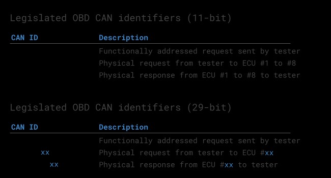
OBD2 CAN Identifiers (11-bit, 29-bit)
All OBD2 communication is structured around a request-response message exchange.
In most passenger cars, 11-bit CAN IDs are predominantly used for OBD2 communication. The ‘Functional Addressing’ ID, 0x7DF, is commonly employed. This ID serves to query all OBD2-compliant Electronic Control Units (ECUs) to determine if they have data to report for the requested parameter (as detailed in ISO 15765-4). Conversely, CAN IDs in the range 0x7E0-0x7E7 are available for ‘Physical Addressing’ requests, allowing direct communication with specific ECUs, though this is less frequently used.
ECUs respond using 11-bit IDs in the range 0x7E8-0x7EF. The most frequently encountered response ID is 0x7E8 (associated with the ECM, Engine Control Module), followed by 0x7E9 (often linked to the TCM, Transmission Control Module).
In certain vehicle types, particularly vans and light, medium, and heavy-duty vehicles, extended 29-bit CAN identifiers may be used for OBD2 communication instead of the standard 11-bit IDs.
For 29-bit CAN, the ‘Functional Addressing’ CAN ID is 0x18DB33F1.
Corresponding responses will typically use CAN IDs ranging from 0x18DAF100 to 0x18DAF1FF (common examples include 0x18DAF110 and 0x18DAF11E). The response ID is also sometimes represented in the ‘J1939 PGN’ format, specifically PGN 0xDA00 (55808), which is designated in the J1939-71 standard as ‘Reserved for ISO 15765-2’.
Diagram illustrating the request-response frame structure in OBD2 protocols, emphasizing PID data parameters.
 OBD2 OBD CAN bus Identifiers 7DF 7E8 7E0
Visual comparison highlighting the distinction between OBD2 and proprietary CAN bus protocols used in vehicles.
OBD2 vs. Proprietary CAN Protocols
It’s crucial to understand that your vehicle’s Electronic Control Units (ECUs) operate primarily using OEM-specific proprietary CAN protocols, not OBD2, for their core functions. Each Original Equipment Manufacturer (OEM) develops and implements its own unique CAN protocols, which can vary significantly depending on the vehicle brand, model, and year of manufacture. Access to and interpretation of this proprietary data is typically restricted to the OEM, unless reverse engineering techniques are employed (reverse engineering methods).
Connecting a CAN bus data logger to your vehicle’s OBD2 connector might reveal OEM-specific CAN data being broadcast, often at high frequencies of 1000-2000 frames per second. However, many newer vehicles incorporate a ‘gateway’ system that blocks access to this raw CAN data through the OBD2 port, allowing only standardized OBD2 communication.
In essence, OBD2 should be considered as an ‘additional’ higher-layer protocol that operates in parallel with the OEM-specific protocol. It’s a standardized overlay for diagnostic purposes, not the fundamental communication system of the vehicle itself.
Bit-rate and ID Validation
As previously mentioned, OBD2 communication can utilize two different bit-rates (250K, 500K) and two CAN ID lengths (11-bit, 29-bit), resulting in four potential protocol combinations. In contemporary vehicles, the combination of 500K bit-rate and 11-bit IDs is the most prevalent. However, external diagnostic tools should systematically verify these parameters to ensure correct communication.
ISO 15765-4 provides guidelines for a standardized initialization sequence to automatically determine the appropriate protocol combination. This process, illustrated in the flowchart below, leverages the requirement that OBD2-compliant vehicles must respond to a specific mandatory OBD2 request (further detailed in the OBD2 PID section). The method also accounts for the fact that transmitting data at an incorrect bit-rate will result in CAN error frames, allowing for bit-rate detection.
Modern iterations of ISO 15765-4 acknowledge that vehicles may support OBD communication via either OBDonUDS or the traditional OBDonEDS. This article primarily focuses on OBD2/OBDonEDS (OBD on Emission Diagnostic Service as defined in ISO 15031-5/SAE J1979) as opposed to WWH-OBD/OBDonUDS (OBD on Unified Diagnostic Service as per ISO 14229, ISO 27145-3/SAE J1979-2).
To differentiate between OBDonEDS and OBDonUDS protocols, diagnostic tools may send additional request messages, specifically UDS requests using 11-bit/29-bit functional address IDs for service 0x22 and Data Identifier (DID) 0xF810 (protocol identification). Vehicles supporting OBDonUDS are required to have ECUs that respond to this specific DID.
Currently, OBDonEDS (also known as OBD2, SAE OBD, EOBD, or ISO OBD) is the dominant protocol in most non-electric vehicles, while WWH-OBD is primarily implemented in EU trucks and buses.
Flowchart outlining the process for OBD2 bit-rate and CAN ID validation as per ISO 15765-4 standard.
Diagram illustrating the five main lower-layer OBD2 protocols: CAN (ISO 15765), KWP2000, SAE J1850 (VPW & PWM), and ISO 9141.
Five Lower-Layer OBD2 Protocols
While CAN (ISO 15765) is the dominant lower-layer protocol for OBD2 in modern vehicles, particularly those manufactured post-2008, it’s important to recognize that older vehicles may utilize one of four other protocols. Examining the OBD2 connector pinouts can often provide clues about which protocol a vehicle might be using.
The five lower-layer OBD2 protocols include:
- ISO 15765 (CAN bus): Mandatory in US vehicles since 2008 and currently the most widely used protocol.
- ISO 14230-4 (KWP2000): Keyword Protocol 2000, frequently used in vehicles manufactured around 2003 onwards, particularly in Asia.
- ISO 9141-2: Common in European, Chrysler, and Asian vehicles produced in the early 2000s (approximately 2000-2004).
- SAE J1850 (VPW – Variable Pulse Width Modulation): Primarily used in older General Motors (GM) vehicles.
- SAE J1850 (PWM – Pulse Width Modulation): Predominantly found in older Ford vehicles.
Transporting OBD2 Messages via ISO-TP (ISO 15765-2)
All OBD2 data communication over CAN bus relies on a transport protocol called ISO-TP (ISO 15765-2). This protocol is essential because it enables the transmission of data payloads exceeding the standard 8-byte limit of a CAN frame. This capability is particularly necessary in OBD2 for operations like retrieving the Vehicle Identification Number (VIN) or Diagnostic Trouble Codes (DTCs), which often require larger data packets. ISO 15765-2 manages this through segmentation, flow control, and reassembly of messages. For a more detailed explanation, refer to our introduction to UDS protocol.
However, a significant portion of OBD2 data exchanges can fit within a single CAN frame. In these cases, ISO 15765-2 specifies the use of a ‘Single Frame’ (SF) format. In a Single Frame, the first data byte (known as the PCI field – Protocol Control Information) indicates the payload length (excluding any padding), leaving 7 bytes available for the actual OBD2 communication content.
Diagram illustrating the different frame types defined by ISO 15765-2 (ISO-TP) for OBD2 communication, including Single Frame, First Frame, Consecutive Frame and Flow Control Frame.
Understanding OBD2 Diagnostic Messages (SAE J1979, ISO 15031-5)
To fully grasp OBD2 communication over CAN, let’s examine the structure of a raw ‘Single Frame’ OBD2 CAN message. In simplified terms, an OBD2 message comprises a CAN identifier, a data length indicator (PCI field), and the actual data payload. The payload itself is further structured into a Mode byte, a Parameter ID (PID), and subsequent data bytes.
Breakdown of an OBD2 message structure, illustrating the components: CAN ID, PCI field, Mode, PID, and Data Bytes.
Example: OBD2 Request/Response
Before dissecting each component of an OBD2 message, let’s consider a practical example: requesting and receiving vehicle speed data.
In this scenario, an external diagnostic tool sends a request message to the vehicle. This message utilizes CAN ID 0x7DF and contains a 2-byte payload: Mode 0x01 and PID 0x0D. The vehicle responds with a message using CAN ID 0x7E8 and a 3-byte payload. This payload includes the vehicle speed value in the 4th byte of the CAN data frame, represented as 0x32 (which is 50 in decimal).
By consulting the OBD2 PID decoding specifications for PID 0x0D, we can determine that the physical value of 50 corresponds to a vehicle speed of 50 km/h.
In the following sections, we will delve deeper into OBD2 modes and PIDs.
Example of an OBD2 request (CAN ID 7DF) and response (CAN ID 7E8) sequence for vehicle speed, highlighting Mode and PID values.
Detailed example focusing on OBD2 PID 0x0D (Vehicle Speed), showing request and response data bytes and their interpretation.
Infographic listing and briefly describing the 10 standardized OBD2 service modes or diagnostic modes.
The 10 OBD2 Services (aka Modes)
OBD2 protocols define 10 diagnostic services, commonly referred to as modes. Mode 0x01 is used to retrieve current, real-time data parameters, while other modes are designed for tasks such as accessing and clearing Diagnostic Trouble Codes (DTCs) or obtaining freeze frame data (snapshots of data when a DTC was set).
It’s important to note that vehicles are not required to support all 10 OBD2 modes. Furthermore, manufacturers may implement additional modes beyond these 10 standardized ones, known as OEM-specific OBD2 modes, for enhanced diagnostics or proprietary functionalities.
In OBD2 messages, the mode is indicated in the second byte of the data payload. In a request message, the mode is included directly (e.g., 0x01 for Mode 1). However, in a response message, 0x40 is added to the requested mode value (e.g., a response to Mode 0x01 will have a mode byte of 0x41).
OBD2 Parameter IDs (PIDs)
Within each OBD2 mode, there are Parameter IDs (PIDs). These PIDs are essentially codes that identify specific data parameters or diagnostic information that can be requested from the vehicle.
For instance, Mode 0x01 encompasses approximately 200 standardized PIDs that provide real-time data on a wide range of vehicle parameters, including speed, engine RPM, and fuel level. However, it’s crucial to understand that vehicles are not obligated to support all PIDs within a given mode. In practice, most vehicles only support a subset of the available PIDs.
Among the PIDs, one stands out as particularly significant: PID 0x00 in Mode 0x01.
If an emissions-related ECU is OBD2 compliant and supports any OBD2 services, it must support Mode 0x01 PID 0x00. When this PID is requested, the vehicle’s ECU responds by indicating which PIDs in the range 0x01-0x20 it supports. This makes PID 0x00 an invaluable tool for initially determining OBD2 compatibility and identifying supported parameters. Similarly, PIDs 0x20, 0x40, 0x60, 0x80, 0xA0, and 0xC0 are used to determine support for subsequent ranges of Mode 0x01 PIDs (0x21-0x40, 0x41-0x60, and so on, up to 0xE1-0x100).
(Repeated image – already used above)
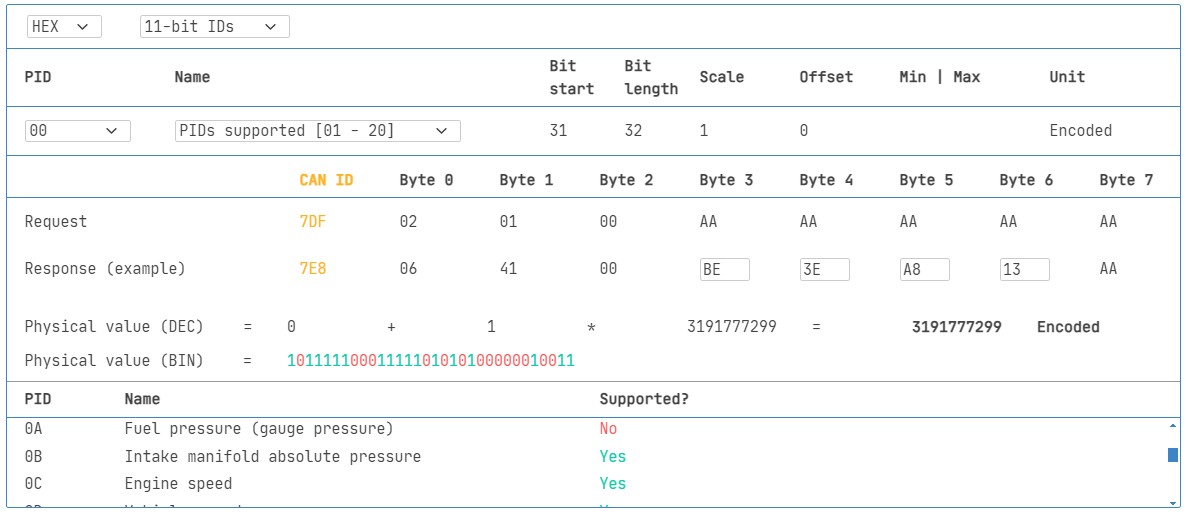
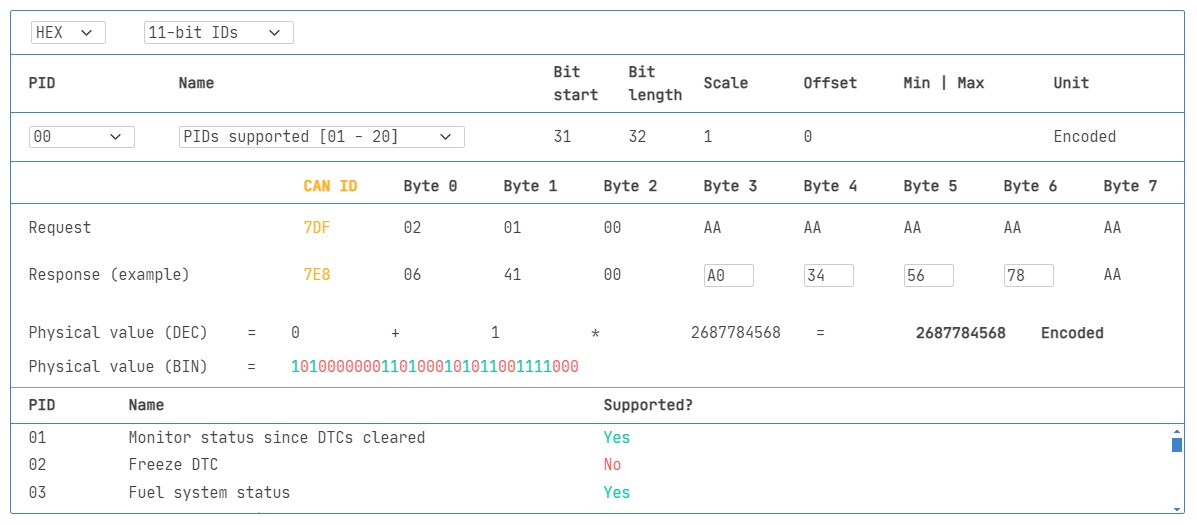 OBD2 PID overview tool
Screenshot of an OBD2 PID overview tool, showing Service 01 parameters and options.
Tip: OBD2 PID Overview Tool
The appendices of SAE J1979 and ISO 15031-5 standards provide essential scaling and decoding information for standard OBD2 PIDs. This information is crucial for converting raw OBD2 data into meaningful physical values, as explained in our CAN bus introduction.
For quick lookup of Mode 0x01 PIDs, our OBD2 PID overview tool is a valuable resource. This tool aids in constructing OBD2 request frames and dynamically decoding OBD2 responses, simplifying the process of interpreting vehicle data.
OBD2 PID overview tool
Practical Guide: Logging and Decoding OBD2 Data
This section provides a hands-on example of how to log OBD2 data using the CANedge CAN bus data logger.
The CANedge offers the flexibility to configure custom CAN frames for transmission, making it ideally suited for OBD2 data logging applications.
Once configured, the CANedge can be easily connected to your vehicle’s OBD2 port using our OBD2-DB9 adapter cable.
Diagram illustrating the setup for OBD2 data logging using a CANedge data logger, showing request and response CAN IDs (7DF and 7E8).
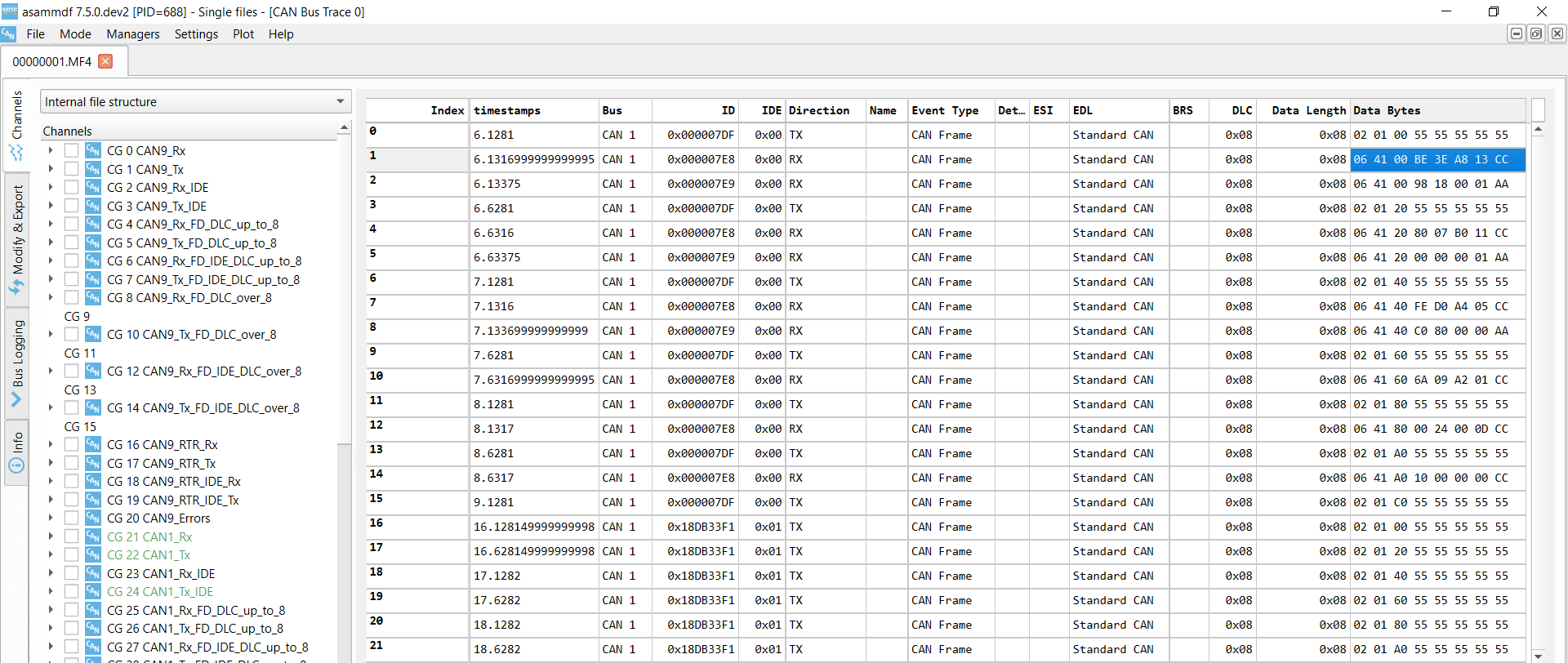 OBD2 Supported PIDs Test Screenshot from asammdf software displaying OBD2 validation PID test responses, showing supported PIDs.
 Review supported PIDs via OBD2 lookup tool
Step 1: Test Bit-rate, IDs & Supported PIDs
As previously discussed, ISO 15765-4 outlines a procedure to determine the correct bit-rate and CAN IDs for OBD2 communication in a specific vehicle. You can perform these tests using the CANedge data logger as described below (refer to the CANedge Intro guide for detailed instructions):
- Bit-rate Test: Initially, attempt to send a CAN frame at 500K bit-rate. Verify if the transmission is successful. If unsuccessful, repeat the test at 250K bit-rate.
- Bit-rate Confirmation: Once a successful transmission is established, use the confirmed bit-rate for all subsequent OBD2 communication.
- Supported PIDs Discovery: Send multiple ‘Supported PIDs’ requests (Mode 0x01 PID 0x00, PID 0x20, etc.) and analyze the responses received.
- CAN ID Type Determination: Based on the response CAN IDs observed (e.g., 11-bit IDs like 0x7E8 or 29-bit IDs like 0x18DAF110), determine whether the vehicle uses 11-bit or 29-bit CAN identifiers for OBD2.
- Supported PID Identification: Examine the data bytes in the responses to ‘Supported PIDs’ requests to identify the specific PIDs supported by the vehicle’s ECUs.
We offer pre-configured CANedge configurations to streamline these initial tests, making the setup process plug-and-play.
Typically, most non-electric vehicles manufactured from 2008 onwards support between 40 to 80 PIDs, utilizing a 500K bit-rate, 11-bit CAN IDs, and the OBD2/OBDonEDS protocol.
As illustrated in the asammdf GUI screenshot, it’s common to receive multiple responses to a single OBD request, particularly when using the functional request ID 0x7DF. This is because 0x7DF is a broadcast request that polls all ECUs for a response. Since all OBD2/OBDonEDS compliant ECUs must support service 0x01 PID 0x00, you will often see numerous responses to this PID. As you proceed with subsequent ‘Supported PIDs’ requests (PID 0x20, 0x40, etc.), the number of responding ECUs generally decreases. Notice in the example that the ECM ECU (0x7E8) supports all the PIDs reported by other ECUs. This suggests that to reduce busload, you could target requests specifically to the ECM using ‘Physical Addressing’ with CAN ID 0x7E0 for subsequent communication, instead of broadcasting to all ECUs.
Step 2: Configure OBD2 PID Requests
Having identified the PIDs supported by your vehicle and the appropriate bit-rate and CAN IDs, the next step is to configure your CANedge transmit list to request the specific PIDs of interest.
Consider these factors when configuring your PID requests:
- CAN IDs: For more efficient communication, switch to ‘Physical Addressing’ request IDs (e.g., 0x7E0) to target requests directly to specific ECUs and avoid redundant responses from multiple ECUs.
- Request Spacing: Introduce a delay of 300-500 milliseconds between consecutive OBD2 requests. Overly rapid requests (spamming) can sometimes cause ECUs to become unresponsive.
- Power Management: Implement triggers in your CANedge configuration to stop PID transmissions when the vehicle is inactive. This prevents unnecessary battery drain by avoiding continuous ‘wake-up’ calls to the ECUs.
- Data Filtering: Configure filters on your CANedge to record only OBD2 response messages. This is particularly useful if your vehicle also broadcasts OEM-specific CAN data, allowing you to focus solely on the relevant OBD2 information.
Once these configurations are set, your CANedge is ready to log raw OBD2 data efficiently.
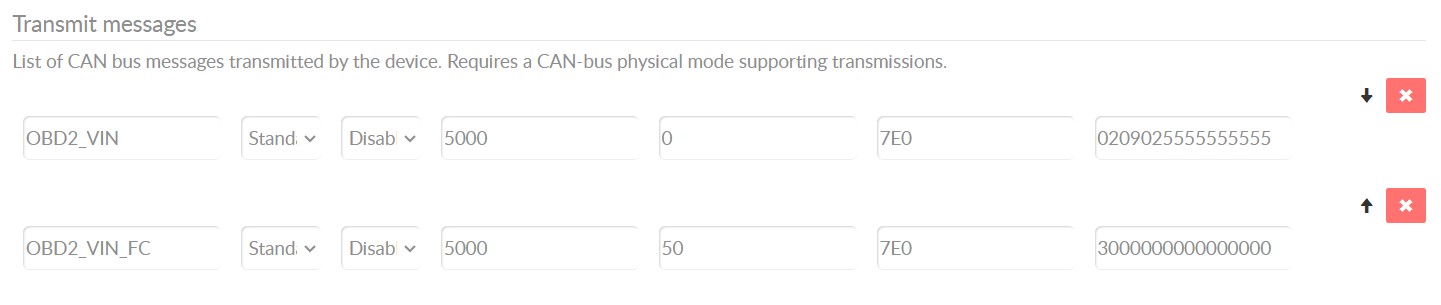
 obd2-transmit-list-example-canedge
Example configuration of a CANedge transmit list for OBD2 PID requests, showing PIDs and CAN IDs.
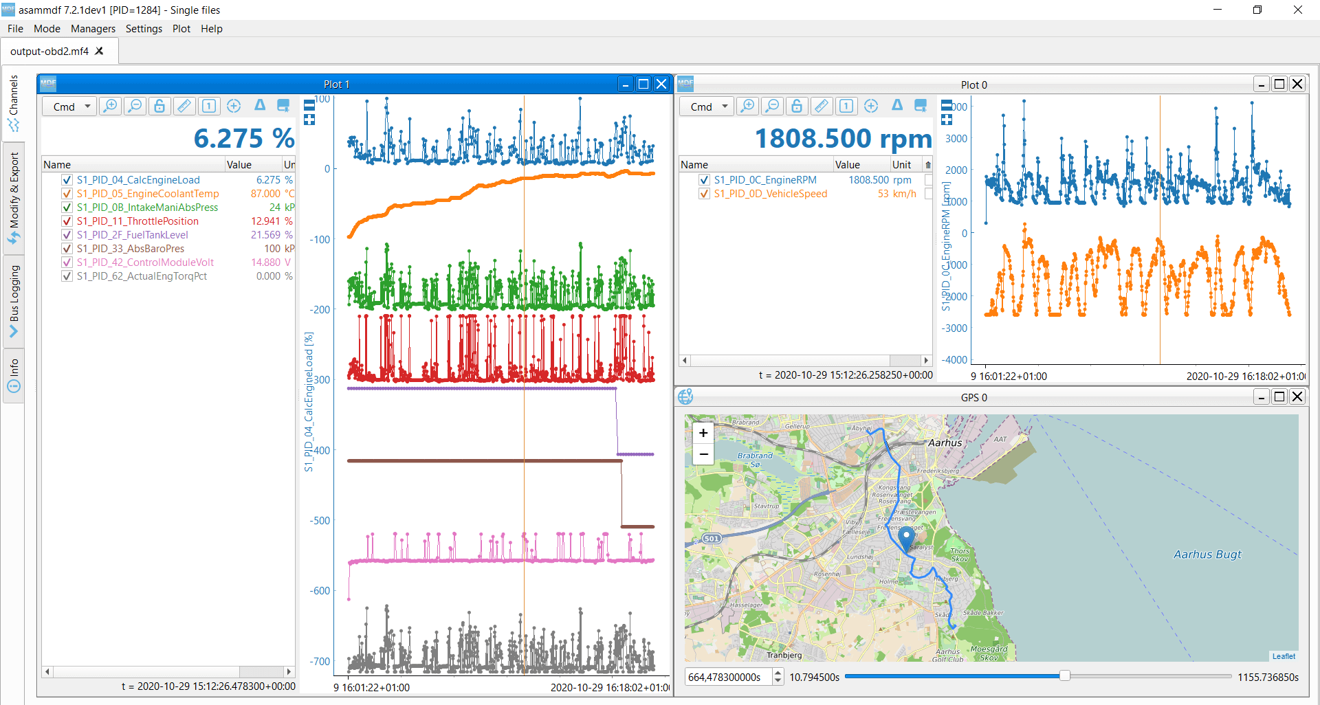 OBD2 data decoded visual plot asammdf CAN bus DBC file
Screenshot from asammdf software displaying DBC-decoded and visualized OBD2 data logged by CANedge, showing plotted parameters.
Step 3: DBC Decode Raw OBD2 Data
To analyze and visualize your logged OBD2 data, you need to decode the raw data bytes into ‘physical values’ (e.g., km/h, °C, RPM).
The necessary decoding information is specified in ISO 15031-5/SAE J1979 standards and is also readily available on resources like Wikipedia. For convenience, we provide a free OBD2 DBC file. This DBC file simplifies the process of DBC decoding raw OBD2 data within most CAN bus software tools.
Decoding OBD2 data is slightly more complex than decoding standard CAN signals. This is because different OBD2 PIDs are transmitted using the same CAN ID (e.g., 0x7E8). Therefore, the CAN ID alone is not sufficient to uniquely identify the signals contained within the payload.
To address this, you must use a combination of the CAN ID, the OBD2 mode, and the OBD2 PID to accurately identify each signal. This method is a form of multiplexing, specifically ‘extended multiplexing,’ which can be effectively implemented using DBC files.
CANedge: Your OBD2 Data Logging Solution
The CANedge offers a straightforward solution for recording OBD2 data directly to an SD card (8-32 GB). Simply connect the CANedge to your vehicle (car, truck, etc.) to begin logging. The logged data can then be decoded using free software and APIs in conjunction with our OBD2 DBC file.
OBD2 logger intro CANedge product page
OBD2 Multi-Frame Communication Examples (ISO-TP)
As established, all OBD2 communication leverages the ISO-TP (Transport Protocol) as defined in ISO 15765-2. While many examples discussed so far involve single-frame communication, this section illustrates examples of multi-frame communication scenarios.
Multi-frame OBD2 exchanges require the use of flow control frames to manage data flow (refer to our UDS introduction for details on flow control). In practice, a common approach is to transmit a static flow control frame approximately 50 milliseconds after the initial request frame, as demonstrated in the CANedge configuration example.
Furthermore, processing multi-frame OBD2 responses requires CAN software or API tools that support ISO-TP, such as the CANedge MF4 decoders, which are capable of reassembling segmented messages.
 OBD2-multi-frame-request-message-vehicle-identification-number
Example trace of an OBD2 multi-frame request message for Vehicle Identification Number (VIN).
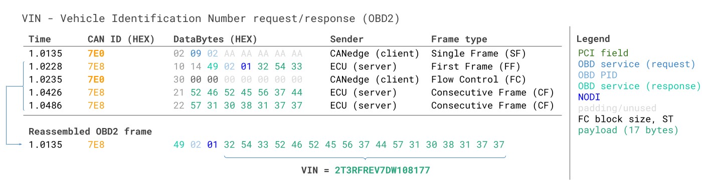
Example 1: OBD2 Vehicle Identification Number (VIN)
Retrieving the Vehicle Identification Number (VIN) is often essential for telematics applications, vehicle diagnostics, and various other use cases (see our UDS protocol introduction for more context). To extract the VIN from a vehicle using OBD2 requests, you utilize Mode 0x09 and PID 0x02.
 VIN Vehicle Identification Number OBD2 Example multi-frame
As shown, the diagnostic tool initiates the process by sending a Single Frame request. This request includes the PCI field (0x02), the request service identifier (0x09), and the PID (0x02).
The vehicle responds with a First Frame. This frame contains the PCI field, the total message length (0x014 = 20 bytes), the mode (0x49, which is 0x09 + 0x40 indicating a response to mode 0x09), and the PID (0x02). Following the PID, the byte 0x01 represents the Number Of Data Items (NODI), which is 1 in this case (refer to ISO 15031-5 / SAE J1979 for detailed specifications). The subsequent 17 bytes contain the VIN itself, encoded in hexadecimal ASCII representation. These hexadecimal values can be converted to standard ASCII characters using methods described in our UDS protocol introduction.
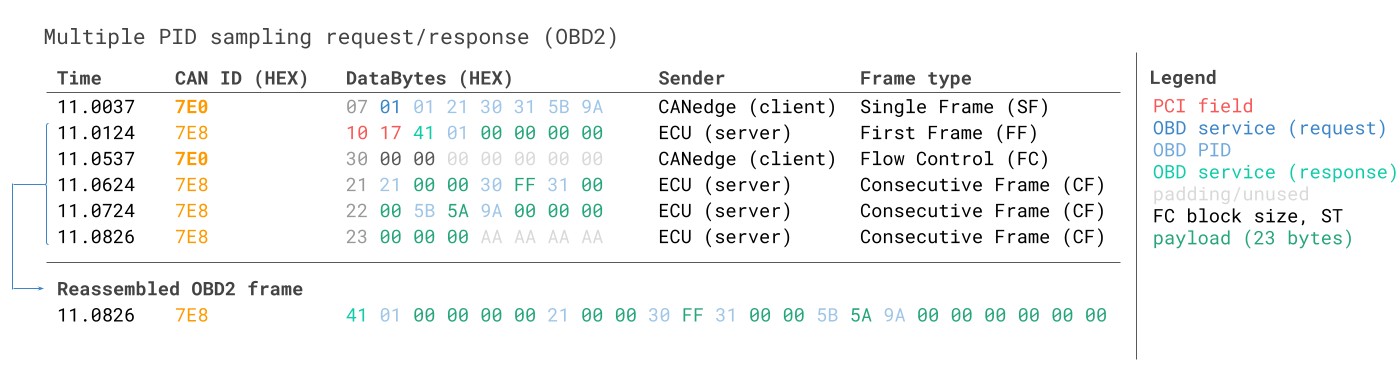
Example 2: OBD2 Multi-PID Request (6x)
OBD2 specifications allow external diagnostic tools to request up to 6 Mode 0x01 OBD2 PIDs within a single request frame. The ECU, in its response, should include data for all supported PIDs from the request (omitting data for any unsupported PIDs). If necessary, the response can span multiple frames using ISO-TP.
This multi-PID request feature offers a more efficient way to collect OBD2 data at higher frequencies, as it reduces the overhead of individual requests. However, it also introduces complexities in data interpretation. The signal encoding in the response becomes specific to the PIDs requested in the initial message, making the use of generic OBD2 DBC files more challenging for such use cases. Therefore, while technically feasible, we generally do not recommend using multi-PID requests in practice for standard OBD2 data logging.
Below is an example trace illustrating a multi-PID request and response:
 Requesting multiple PIDs in one request
The multi-frame response structure is similar to the VIN example, but with the added complexity that the payload includes both the requested PIDs themselves and the corresponding data values for each. In the example trace, the PIDs in the response are ordered in a sequence that mirrors the order in which they were requested, which is a common practice but not strictly mandated by the ISO 15031-5 standard.
Decoding such responses using generic DBC files becomes very difficult in practice. Consequently, we advise against using this approach for practical data logging unless you are utilizing specialized tools that offer built-in support for multi-PID requests. Effectively, you are dealing with an advanced form of extended multiplexing, where the payload structure dynamically changes based on the request. Creating a generalized DBC file to handle this across different vehicles with varying PID support becomes exceedingly complex. Furthermore, if you are sending multiple different multi-PID requests, distinguishing between response messages and associating them with the correct requests solely through DBC manipulation becomes practically impossible.
Workarounds might involve custom scripting and recording both transmit and receive messages. A script could then be designed to interpret response messages in conjunction with their corresponding request messages, enabling dynamic decoding. However, such script-based solutions are often difficult to scale and maintain for broader applications.
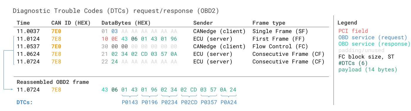
Example 3: OBD2 Diagnostic Trouble Codes (DTCs)
OBD2 can be used to request emissions-related Diagnostic Trouble Codes (DTCs) using Mode 0x03, specifically the ‘Show stored Diagnostic Trouble Codes’ service. No PID is included in the request for this mode. The targeted ECU(s) will respond with the number of DTCs currently stored (which could be zero if no DTCs are active), with each DTC being represented by 2 data bytes. If more than 2 DTCs are stored, multi-frame responses are necessary to transmit all the DTC information.
The 2-byte DTC value is typically structured into two parts, as defined by ISO 15031-5 and ISO 15031-6. The first two bits of the first byte define the ‘category’ of the DTC (e.g., Powertrain, Chassis, Body, Network), while the remaining 14 bits form a 4-digit code (displayed in hexadecimal format). The decoded DTC values can be looked up in various online OBD2 DTC lookup tools, such as repairpal.com, to obtain a textual description of the fault.
The example below illustrates a request to an ECU that has 6 DTCs stored.
Diagram illustrating the interpretation and decoding process of OBD2 Diagnostic Trouble Codes (DTCs), showing the 2-byte structure and category breakdown.
 OBD2 Diagnostic Trouble Codes DTC CAN Bus Request Response Example
OBD2 Data Logging – Use Case Examples
OBD2 data, particularly from cars and light trucks, has a wide array of practical applications across various industries:
Logging data from cars
OBD2 data logging in passenger cars can be leveraged for diverse purposes, including optimizing fuel efficiency, improving driving behavior, testing and validating prototype automotive components, and usage-based insurance models.
OBD2 logger product page
Real-time car diagnostics
OBD2 interfaces facilitate real-time streaming of vehicle diagnostic data in a human-readable format. This is invaluable for quickly diagnosing vehicle issues, monitoring system performance, and conducting on-the-spot troubleshooting.
OBD2 streaming interface product page
Predictive maintenance
Integrating OBD2 data with IoT (Internet of Things) solutions enables remote vehicle monitoring and predictive maintenance strategies for cars and light trucks. By continuously analyzing OBD2 data in the cloud, potential breakdowns can be predicted and proactively addressed, minimizing downtime and repair costs.
Predictive maintenance solution page
Vehicle blackbox logger
An OBD2 logger can serve as a ‘black box’ recorder for vehicles or various types of equipment. This provides valuable data logging capabilities for incident reconstruction, warranty claim validation, and in-depth diagnostic analysis in case of disputes or failures.
CAN bus blackbox logger product page
Do you have a specific OBD2 data logging use case in mind? We encourage you to reach out to us for a free consultation and expert guidance!
Contact us
For further introductory resources, explore our comprehensive guides section or download the ‘Ultimate Guide to CAN bus’ PDF.
Ready to start logging or streaming OBD2 data?
Get your OBD2 data logger today!
Buy now Contact us for inquiries
Recommended for you
OBD2 DATA LOGGER: EASILY LOG & CONVERT OBD2 DATA
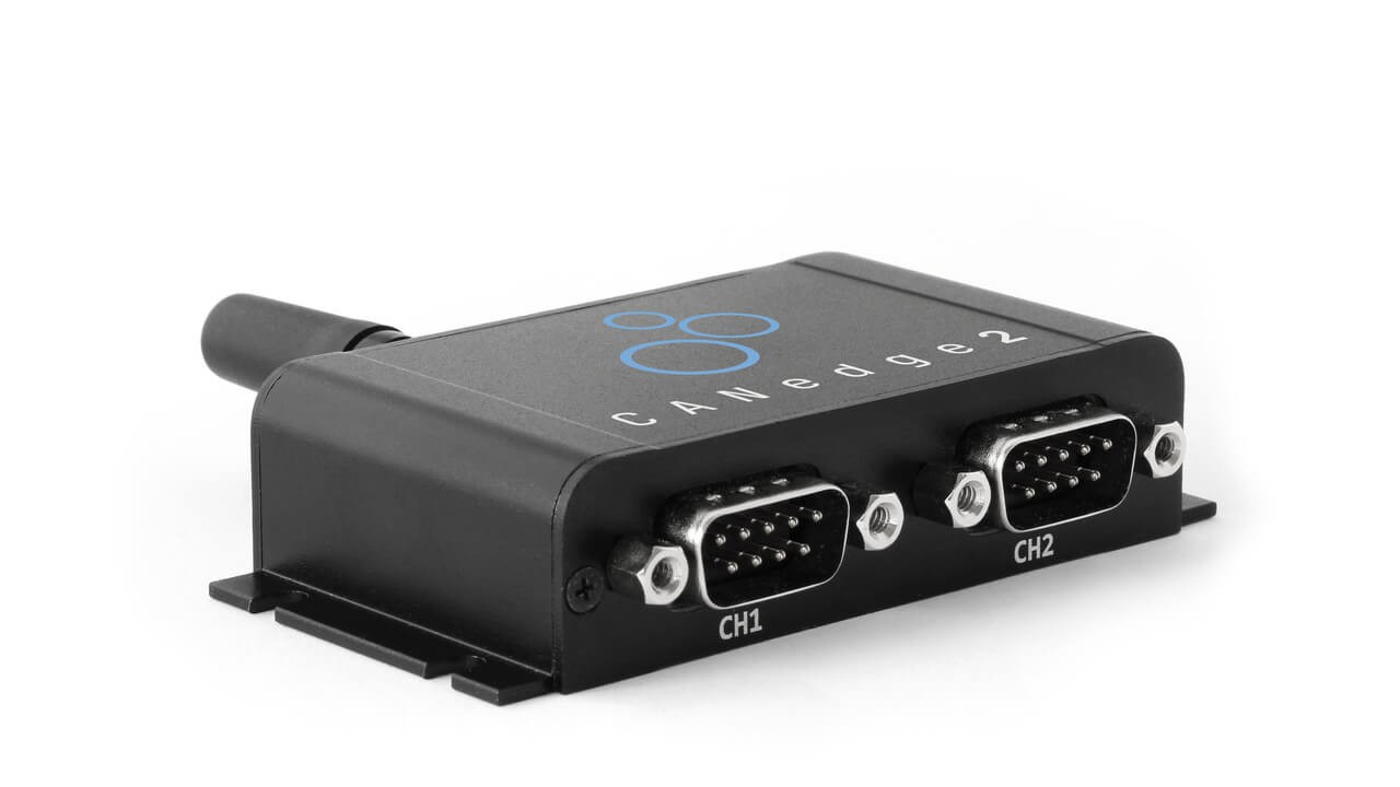 CANedge2 – Dual CAN Bus Telematics Dongle CANEDGE2 – PRO CAN IoT LOGGER
[