In the world of modern automotive repair and diagnostics, the OBD2 connector stands as a critical interface. This guide will delve into the essentials of the On-Board Diagnostics II (OBD2) connector, a standardized port that grants access to your vehicle’s self-diagnostic system. Whether you’re a seasoned mechanic or a curious car owner, understanding the OBD2 connector is key to unlocking valuable insights into your vehicle’s health and performance.
This practical introduction covers everything from the OBD2 connector’s location and pinout to its role in accessing crucial vehicle data. We’ll explore how this port facilitates communication with your car’s computer, enabling the retrieval of diagnostic trouble codes (DTCs) and real-time parameters.
Continue reading to discover why this has become a go-to resource for understanding the OBD2 connector and its significance in modern automotive technology.
You can also watch our OBD2 intro video above – or get the PDF
What is the OBD2 Connector?
The OBD2 connector is a standardized 16-pin port within your vehicle that serves as the gateway to its On-Board Diagnostic system. This system, known as OBD2, is essentially your car’s built-in health monitor. It allows mechanics and vehicle owners to retrieve diagnostic trouble codes (DTCs) and access live data streams, all through this single, standardized connector.
You’ve likely encountered the OBD2 system indirectly if you’ve ever seen the check engine light illuminate on your dashboard. This light is an alert from your car’s OBD2 system, signaling a potential issue. To investigate further, a mechanic uses an OBD2 scanner. This tool is plugged into the OBD2 16 pin connector, typically located within easy reach under the dashboard, often near the steering column.
The OBD2 scanner then sends ‘OBD2 requests’ through the connector. In response, the car sends back ‘OBD2 responses’. These responses can contain a wealth of information, including vehicle speed, fuel level, and those critical Diagnostic Trouble Codes (DTCs). This communication via the OBD2 connector is what makes diagnosing and troubleshooting vehicle problems faster and more efficient.
Image alt text: Malfunction Indicator Light (MIL) or Check Engine Light illuminated on a car dashboard, indicating an OBD2 system alert and the need for diagnostics using a scan tool connected to the OBD2 port.
Does Your Car Have an OBD2 Connector?
The answer is almost certainly yes, especially if you own a non-electric car manufactured in recent decades. The standardization of OBD2 has been progressively implemented worldwide, making it a near-universal feature in modern vehicles. However, it’s worth noting that the presence of a 16-pin OBD2 connector doesn’t automatically guarantee OBD2 compliance, particularly in older models. Some older cars might feature the connector without fully supporting the OBD2 protocol.
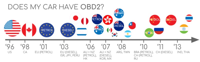
To confirm OBD2 compliance, consider the vehicle’s origin and the year it was first purchased new:
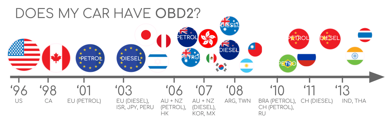 Does My Car Have OBD2?
Image alt text: Chart outlining OBD2 compliance by region and vehicle type, highlighting the years OBD2 became mandatory in the US and EU for gasoline and diesel cars, and light, medium, and heavy-duty vehicles.
A Brief History of the OBD2 Connector and Standard
The journey of the OBD2 connector and its associated standards began in California. The California Air Resources Board (CARB) mandated OBD systems in all new cars from 1991 onwards, primarily for emission control.
The Society of Automotive Engineers (SAE) played a crucial role in formalizing this by recommending the OBD2 standard. This led to the standardization of DTCs and, importantly, the OBD connector itself across different vehicle manufacturers through the SAE J1962 standard.
The OBD2 standard and connector were then adopted globally in phases:
- 1996: OBD2 became mandatory in the USA for all cars and light trucks.
- 2001: The EU made OBD2 mandatory for gasoline cars.
- 2003: OBD2 compliance was extended to diesel cars in the EU (known as EOBD).
- 2005: OBD2 requirements in the US expanded to medium-duty vehicles.
- 2008: US vehicles were required to use ISO 15765-4 (CAN) as the foundation for OBD2 communication.
- 2010: OBD2 became mandatory for heavy-duty vehicles in the US.
Image alt text: Diagram illustrating the history of OBD2 development and its connection to emission control, exhaust regulations, and the evolution from EOBD to EOBDII standards in automotive diagnostics.
Image alt text: Timeline infographic summarizing the historical milestones of OBD2 standardization and implementation across different years and regions, from its inception to widespread adoption.
Image alt text: Conceptual graphic representing the future of OBD3, highlighting trends towards remote diagnostics, emissions testing, cloud connectivity, and integration with IoT (Internet of Things) technologies.
The Future of OBD2 and the OBD2 Connector
While the OBD2 connector and standard are firmly established, the automotive landscape is evolving. Interestingly, electric vehicles (EVs), due to their different emission profiles, aren’t mandated to support OBD2 in the same way as combustion engine vehicles. In fact, most modern EVs don’t support standard OBD2 requests, opting instead for OEM-specific UDS communication protocols. This often makes accessing data from EVs challenging without specialized knowledge or reverse engineering, as highlighted in case studies for electric cars including Tesla, Hyundai/Kia, Nissan and VW/Skoda EVs.
Recognizing the limitations of current OBD2 implementations in data richness and lower-layer protocols, advancements like WWH-OBD (World Wide Harmonized OBD) and OBDonUDS (OBD on UDS) are emerging. These aim to refine OBD communication using the UDS protocol as a foundation. For deeper insight into these protocols, refer to our introduction to UDS.
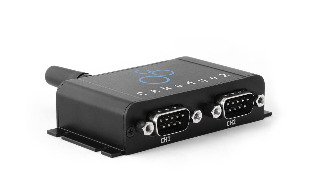
The concept of OBD3 envisions integrating telematics into all vehicles, making emission checks more efficient and less manual. OBD3 proposes adding a radio transponder to vehicles, enabling wireless transmission of the vehicle identification number (VIN) and DTCs to a central server for automated checks. Technologies like the CANedge2 WiFi CAN logger and CANedge3 3G/4G CAN logger already facilitate wireless data transfer, paving the way for such advancements. However, privacy and surveillance concerns remain a significant hurdle for widespread OBD3 adoption.
The traditional role of OBD2, designed for emission controls in repair shops, is also being challenged by the increasing use of OBD2 data by third parties via OBD2 dongles and CAN loggers. The German car industry, as an example, is exploring ways to limit third-party access to OBD2 data, as highlighted by Christoph Grote, SVP Electronics, BMW (2017):
“OBD has been designed to service cars in repair shops. In no way has it been intended to allow third parties to build a form of data-driven economy on the access through this interface“
The proposal to potentially disable OBD2 functionality during normal driving and centralize data collection with manufacturers raises questions about control over ‘automotive big data’. While security concerns, such as car hacking risks, are cited, many perceive this as a commercially motivated move, potentially disrupting the market for third-party OBD2 services, as discussed by navixy.com.
Image alt text: Visual representation of the future trend where electric vehicles may restrict or block access to data through the OBD2 connector, emphasizing a shift in data accessibility.
Enhance Your CAN Bus Expertise
Eager to become a CAN bus expert?
Access our comprehensive collection of 12 ‘simple intros’ in a 160+ page PDF guide:
Download now
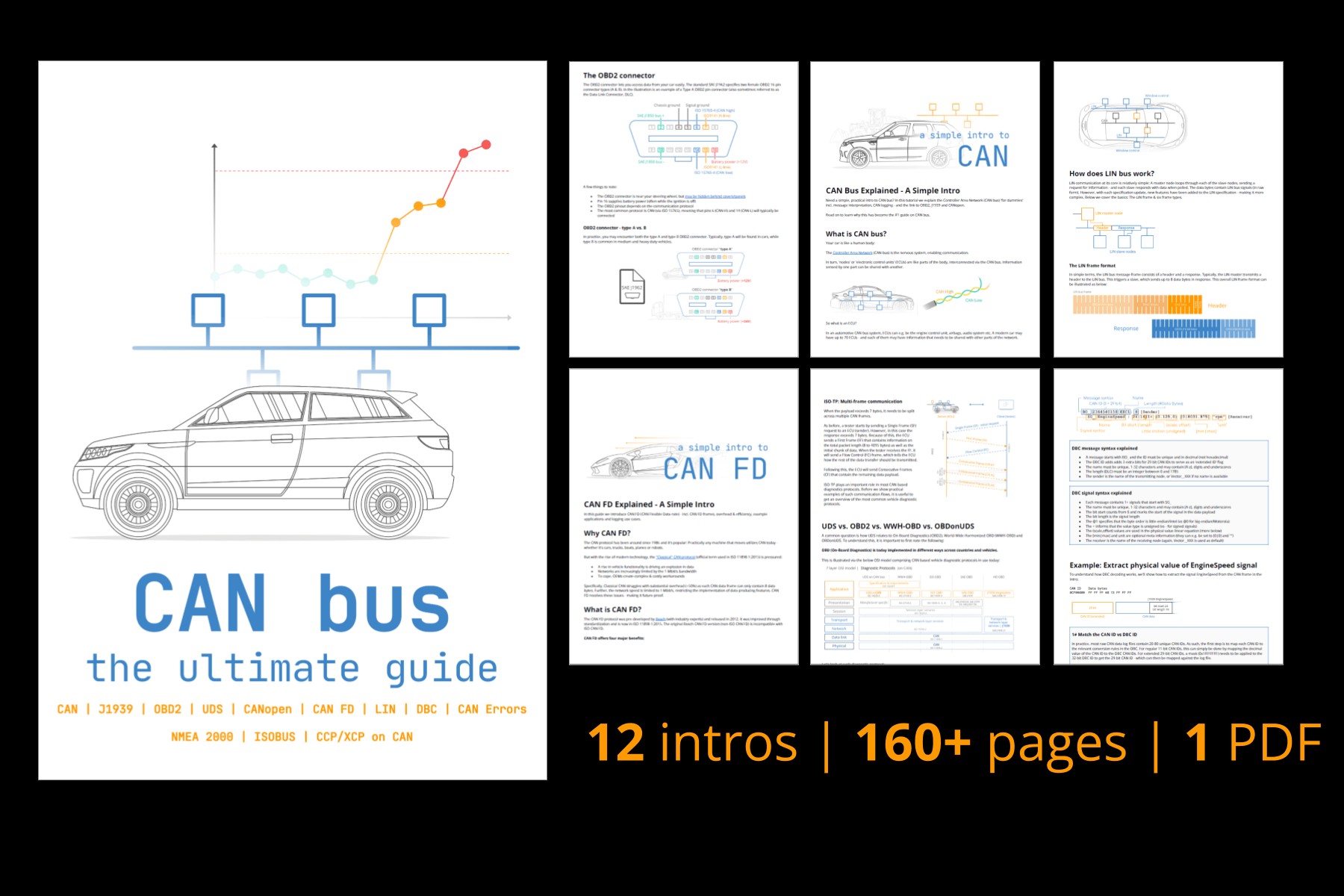 CAN Bus – The Ultimate Guide Tutorial PDF
OBD2 Standards and the Connector
On-board diagnostics, OBD2, operates as a higher layer protocol – a language of communication – while CAN (Controller Area Network) functions as the communication method itself, akin to a phone line. OBD2 shares this framework with other CAN-based higher-layer protocols like J1939, CANopen, and NMEA 2000.
The OBD2 standards are comprehensive, specifying not only the OBD2 connector but also the lower-layer protocols, OBD2 parameter IDs (PIDs), and more. These standards can be categorized within a 7-layer OSI model, with SAE and ISO standards covering various layers, reflecting the standardization efforts in the USA (SAE) and EU (ISO). Notably, several standards are technically very similar, such as SAE J1979 and ISO 15031-5, and SAE J1962 and ISO 15031-3.
Image alt text: Diagram comparing OBD2 and CAN Bus within the 7-layer OSI model, highlighting relevant ISO and SAE standards like ISO 15765 and ISO 11898 at different layers of the communication protocol.
Image alt text: OBD2 connector pinout diagram for a female Type A socket, detailing pin assignments for various functions within the Data Link Connector (DLC).
The OBD2 Connector Pinout: SAE J1962 Standard
The 16-pin OBD2 connector, standardized under SAE J1962 / ISO 15031-3, provides straightforward access to your vehicle’s data. The illustration above shows a typical Type A OBD2 pin connector, also known as a Data Link Connector (DLC).
Key aspects of the OBD2 connector include:
- Location: Usually positioned near the steering wheel, though its exact location can sometimes be hidden.
- Pin 16: Supplies battery power, often even when the ignition is off, which is crucial for scanners and loggers.
- Pinout Variability: The specific OBD2 pinout configuration depends on the communication protocol used by the vehicle.
- CAN Bus Integration: In most modern vehicles, CAN bus is the primary lower-layer protocol. This means pins 6 (CAN-High) and 14 (CAN-Low) are typically active and connected.
OBD2 Connector Types: Type A vs. Type B
In practical applications, you may encounter both Type A and Type B OBD2 connectors. Type A is predominantly found in cars and light-duty vehicles, while Type B is more common in medium and heavy-duty vehicles.
While both types share a similar OBD2 pinout structure, they differ in their power supply outputs – 12V for Type A and 24V for Type B. Baud rates can also vary, with cars typically using 500K and heavy-duty vehicles often using 250K (though 500K support is increasing in heavy-duty applications).
A key physical differentiator is the interrupted groove in the middle of the Type B OBD2 connector. This design feature means a Type B OBD2 adapter cable is universally compatible with both Type A and Type B sockets, whereas a Type A adapter will not fit into a Type B socket.
Image alt text: Comparison diagram of OBD2 Connector Type A and Type B as per SAE J1962, highlighting differences in voltage (12V vs 24V) and typical vehicle applications (car/van vs truck).
Image alt text: Diagram illustrating the relationship between OBD2 and CAN bus under the ISO 15765 standard, showing how CAN bus serves as the physical and data link layer for OBD2 diagnostics.
OBD2 Communication via CAN Bus: ISO 15765-4
Since 2008, CAN bus has been mandated as the lower-layer protocol for OBD2 in all vehicles sold in the US, as per ISO 15765. ISO 15765-4, also known as Diagnostics over CAN (DoCAN), sets specific constraints on the CAN standard (ISO 11898) to ensure standardized diagnostic communication.
ISO 15765-4 standardizes the CAN interface for diagnostic equipment, focusing on the physical, data link, and network layers. Key specifications include:
- CAN Bus Bit-rate: Must be either 250K or 500K.
- CAN IDs: Supports both 11-bit and 29-bit CAN identifiers.
- OBD CAN IDs: Specific CAN IDs are designated for OBD requests and responses.
- Diagnostic Data Length: Diagnostic CAN frame data length is fixed at 8 bytes.
- OBD2 Adapter Cable Length: The maximum length for an OBD2 adapter cable is 5 meters.
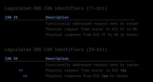
OBD2 CAN Identifiers: 11-bit and 29-bit
OBD2 communication relies on a request-response message structure. In most passenger cars, 11-bit CAN IDs are used for OBD2 communication. The ‘Functional Addressing’ ID, 0x7DF, is commonly used to broadcast requests to all OBD2-compliant ECUs, asking if they have data for the requested parameter (as per ISO 15765-4). ‘Physical Addressing’ requests, using CAN IDs 0x7E0-0x7E7, target specific ECUs but are less frequently used.
ECUs respond using 11-bit IDs in the range of 0x7E8-0x7EF. The most common response ID is 0x7E8 (from the ECM, Engine Control Module), followed by 0x7E9 (from the TCM, Transmission Control Module).
In certain vehicles, especially vans and medium to heavy-duty vehicles, OBD2 communication may utilize extended 29-bit CAN identifiers instead of 11-bit IDs. Here, the ‘Functional Addressing’ CAN ID is 0x18DB33F1. Responses in this format are typically seen with CAN IDs ranging from 0x18DAF100 to 0x18DAF1FF (commonly 18DAF110 and 18DAF11E). These response IDs are sometimes also represented in the ‘J1939 PGN’ format, specifically PGN 0xDA00 (55808), which in the J1939-71 standard is reserved for ISO 15765-2.
Image alt text: Diagram illustrating the OBD2 protocol request and response frame structure, showing the flow of data and parameters between a diagnostic tool and a vehicle’s ECU.
 OBD2 OBD CAN bus Identifiers 7DF 7E8 7E0
Image alt text: Conceptual image contrasting OBD2 CAN bus communication with proprietary OEM-specific CAN bus protocols, illustrating the difference in data accessibility and standardization.
OBD2 vs. OEM Proprietary CAN Protocols
It’s important to understand that your vehicle’s Electronic Control Units (ECUs) operate primarily on OEM-specific proprietary CAN protocols, not OBD2. OBD2 is an additional, standardized layer for diagnostics. OEMs develop their own unique CAN protocols for vehicle functions, often varying by brand, model, and year. This OEM-specific CAN data is generally inaccessible to those outside the manufacturer without significant reverse engineering efforts, as discussed in our guide on CAN bus sniffing and reverse engineering.
When connecting a CAN bus data logger to your car’s OBD2 connector, you might observe OEM-specific CAN data, typically broadcast at high rates (1000-2000 frames/second). However, many newer vehicles employ a ‘gateway’ system that restricts access to this proprietary CAN data through the OBD2 port, allowing only standardized OBD2 communication.
In essence, think of OBD2 as a supplemental higher-layer protocol that operates alongside the OEM-specific protocol. It’s a diagnostic window into the vehicle’s systems, but not the primary language spoken by the car’s internal networks.
Bit-rate and ID Validation for OBD2 Connector Communication
OBD2 over CAN bus can utilize two bit-rates (250K, 500K) and two CAN ID lengths (11-bit, 29-bit), resulting in four potential combinations. Modern cars commonly use 500K with 11-bit IDs. Diagnostic tools should systematically validate these parameters.
ISO 15765-4 outlines a standard initialization sequence to determine the correct combination. This process leverages the fact that OBD2-compliant vehicles must respond to a specific mandatory OBD2 request (detailed in the OBD2 PID section). Incorrect bit-rate transmissions will result in CAN error frames, aiding in identification.
Current versions of ISO 15765-4 also address vehicles supporting OBD communication via OBDonUDS in addition to OBDonEDS. This article primarily focuses on OBD2/OBDonEDS (OBD on Emission Diagnostic Service as per ISO 15031-5/SAE J1979) versus WWH-OBD/OBDonUDS (OBD on Unified Diagnostic Service as per ISO 14229, ISO 27145-3/SAE J1979-2).
To test for OBDonEDS vs OBDonUDS, diagnostic tools may send additional UDS requests with 11-bit/29-bit functional address IDs for service 0x22 and data identifier (DID) 0xF810 (protocol identification). Vehicles supporting OBDonUDS must have ECUs that respond to this DID.
In practice, OBDonEDS (also known as OBD2, SAE OBD, EOBD, or ISO OBD) is prevalent in most non-EV cars today, while WWH-OBD is mainly used in EU trucks and buses.
Image alt text: Flowchart illustrating the OBD2 bit-rate and CAN ID validation process according to ISO 15765-4, guiding diagnostic tools in establishing correct communication parameters with a vehicle.
Image alt text: Graphic depicting the five lower-layer protocols of OBD2, including CAN (ISO 15765), KWP2000, SAE J1850 (VPW and PWM), and ISO 9141, highlighting the diversity of communication standards used in OBD2 systems.
Five Lower-Layer OBD2 Protocols
While CAN (ISO 15765) is now the dominant lower-layer protocol for OBD2, especially in vehicles post-2008, older vehicles may utilize other protocols. Understanding these is useful, particularly when working with pre-2008 models. The OBD2 connector pinout can sometimes indicate the protocol in use.
The five lower-layer protocols include:
- ISO 15765 (CAN bus): Mandatory in US cars since 2008 and the most common protocol today.
- ISO14230-4 (KWP2000): Keyword Protocol 2000, common in 2003+ vehicles, particularly in Asia.
- ISO 9141-2: Used in EU, Chrysler, and Asian cars from 2000-2004.
- SAE J1850 (VPW): Predominantly used in older General Motors (GM) vehicles.
- SAE J1850 (PWM): Primarily used in older Ford vehicles.
ISO-TP for OBD2 Messaging: ISO 15765-2
All OBD2 data exchange over CAN bus relies on ISO-TP (ISO 15765-2), a transport protocol that enables transmission of payloads exceeding 8 bytes, which is the standard CAN frame size. This capability is essential for OBD2 functions like retrieving the Vehicle Identification Number (VIN) or Diagnostic Trouble Codes (DTCs). ISO 15765-2 manages segmentation, flow control, and reassembly of these larger messages. For a detailed explanation, refer to our introduction to UDS.
However, much of the OBD2 data communication fits within a single CAN frame. In these cases, ISO 15765-2 specifies the use of a ‘Single Frame’ (SF). Here, the first data byte (PCI field) indicates the payload length (excluding padding), leaving 7 bytes for OBD2-specific communication.
Image alt text: Diagram illustrating ISO 15765-2 ISO-TP frame types used in OBD2 communication, including Single Frame, First Frame, Consecutive Frame, and Flow Control Frame, detailing their structure and function.
Decoding the OBD2 Diagnostic Message: SAE J1979, ISO 15031-5
To effectively understand OBD2 communication over CAN, let’s examine the structure of a raw ‘Single Frame’ OBD2 CAN message. In simple terms, an OBD2 message consists of an identifier, a data length indicator (PCI field), and the actual data. The data portion is further broken down into Mode, parameter ID (PID), and data bytes.
Image alt text: Breakdown of an OBD2 message structure, explaining the components such as Mode, Parameter ID (PID), Identifier, and Data Bytes within an OBD-II frame.
Example: OBD2 Request and Response
Consider a practical example: requesting ‘Vehicle Speed’. A diagnostic tool sends a request message with CAN ID 0x7DF and 2 payload bytes: Mode 0x01 and PID 0x0D. The vehicle responds with CAN ID 0x7E8 and 3 payload bytes, with the vehicle speed value encoded in the 4th byte, 0x32 (decimal 50).
By consulting the OBD2 PID specifications for 0x0D, we can determine that 0x32 corresponds to a physical value of 50 km/h.
Let’s now delve into OBD2 modes and PIDs in more detail.
Image alt text: Example of an OBD2 request (CAN ID 7DF) and response (CAN ID 7E8) sequence for retrieving Vehicle Speed, illustrating the message exchange between a diagnostic tool and a vehicle.
Image alt text: Example breakdown of OBD2 PID 0D (Vehicle Speed), showing the request and response messages and how to interpret the data bytes to get the vehicle speed value.
Image alt text: Overview of the 10 OBD2 service modes (or modes), detailing their diagnostic services, including retrieving current data, freeze frame data, and clearing diagnostic trouble codes (DTCs).
The 10 OBD2 Service Modes (Diagnostic Services)
OBD2 defines 10 diagnostic services, often referred to as modes. Mode 0x01 is used for accessing current, real-time data, while other modes are designed for retrieving and clearing diagnostic trouble codes (DTCs) or accessing freeze frame data.
Not all OBD2 modes are mandatory for vehicles to support, and manufacturers may also implement OEM-specific modes beyond these 10 standard modes. In OBD2 messages, the mode is indicated in the second byte. In a request message, the mode is directly included (e.g., 0x01), whereas in a response message, 0x40 is added to the mode value (e.g., resulting in 0x41 for a response to mode 0x01).
OBD2 Parameter IDs (PIDs) Explained
Within each OBD2 mode, there are Parameter IDs (PIDs). For instance, mode 0x01 includes approximately 200 standardized PIDs that provide real-time data on parameters like speed, RPM, and fuel level. However, vehicles are not required to support all PIDs within a mode, and typically, only a subset is implemented.
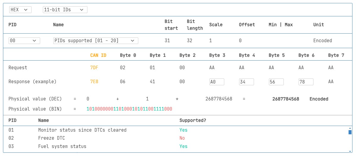
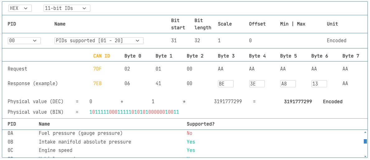
One PID holds particular significance: mode 0x01 PID 0x00. If an emissions-related ECU supports any OBD2 services, it must support mode 0x01 PID 0x00. Responding to this PID, the ECU indicates its support for PIDs 0x01-0x20. This makes PID 0x00 a fundamental test for OBD2 compatibility. Similarly, PIDs 0x20, 0x40, …, 0xC0 are used to determine support for the remaining mode 0x01 PIDs.
Image alt text: Diagram again illustrating the OBD2 protocol request and response frames, emphasizing the role of Parameter IDs (PIDs) in specifying the data being requested and returned in OBD2 communication.
 OBD2 PID overview tool
Image alt text: Screenshot of an OBD2 PID overview tool, showcasing Service 01 and its functionalities for displaying and interacting with OBD2 Parameter IDs.
Practical Tip: OBD2 PID Overview Tool
The appendices of SAE J1979 and ISO 15031-5 detail the scaling information for standard OBD2 PIDs, enabling the conversion of raw data into physical values, as explained in our CAN bus introduction.
For quick lookups of mode 0x01 PIDs, our OBD2 PID overview tool is invaluable. It assists in constructing OBD2 request frames and dynamically decoding OBD2 responses.
OBD2 PID overview tool
Logging and Decoding OBD2 Data: A Practical Guide
This section provides a step-by-step example of logging OBD2 data using the CANedge CAN bus data logger. The CANedge’s customizable CAN frame transmission feature makes it ideal for OBD2 logging.
Connecting the CANedge to your vehicle is straightforward using our OBD2-DB9 adapter cable.
Image alt text: Diagram depicting an OBD2 PID data logger requesting data (CAN ID 7DF) and receiving a response (CAN ID 7E8), illustrating the data logging process for OBD2 parameters.
 OBD2 bit rate test
Image alt text: Screenshot showing a bit-rate validation test for OBD2 communication, confirming successful CAN frame transmission at a specific bit rate.
 OBD2 Supported PIDs Test
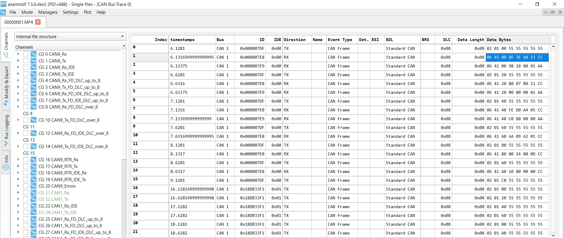
Image alt text: Screenshot from asammdf software displaying OBD2 validation PID test responses, showing how supported PIDs can be reviewed and analyzed.
 Review supported PIDs via OBD2 lookup tool
Step #1: Bit-rate, ID, and Supported PIDs Validation
As per ISO 15765-4, determining the correct bit-rate and IDs for your vehicle is crucial. Use the CANedge to perform these tests (refer to the CANedge Intro for detailed instructions):
- Bit-rate Test: Send a CAN frame at 500K and verify successful transmission. If unsuccessful, try 250K.
- Bit-rate Confirmation: Use the confirmed bit-rate for all subsequent communication.
- Supported PIDs Request: Send multiple ‘Supported PIDs’ requests and analyze the responses.
- ID Type Determination: Response IDs will indicate whether 11-bit or 29-bit IDs are in use.
- PID Support Analysis: Response data will reveal which PIDs are supported by the vehicle.
Pre-configured settings are available to simplify these tests. Most non-EV vehicles manufactured post-2008 typically support 40-80 PIDs, using a 500K bit-rate, 11-bit CAN IDs, and the OBD2/OBDonEDS protocol.
The asammdf GUI screenshot illustrates multiple responses to a single OBD request, common when using the 0x7DF request ID, which polls all ECUs. Since all OBD2/OBDonEDS-compliant ECUs must support service 0x01 PID 0x00, numerous responses are often seen for this PID. As you proceed with subsequent ‘Supported PIDs’ requests, fewer ECUs may respond. Notably, the ECM ECU (0x7E8) often supports all PIDs supported by other ECUs, suggesting that busload can be reduced by directing subsequent requests specifically to the ECM using ‘Physical Addressing’ CAN ID 0x7E0.
Step #2: Configuring OBD2 PID Requests
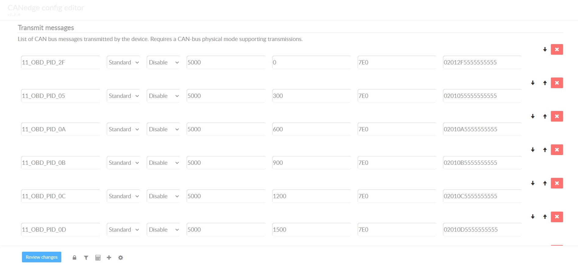
Once you’ve identified supported OBD2 PIDs, bit-rate, and CAN IDs, configure your transmit list with the PIDs you wish to log. Consider these points:
- CAN IDs: Switch to ‘Physical Addressing’ request IDs (e.g., 0x7E0) to minimize redundant responses.
- Request Spacing: Implement a 300-500 ms delay between OBD2 requests to prevent ECU overload and ensure reliable responses.
- Power Management: Use triggers to halt transmissions when the vehicle is inactive, preventing battery drain and unnecessary ECU activation.
- Data Filtering: Apply filters to record only OBD2 responses, particularly if your vehicle also broadcasts OEM-specific CAN data.
With these configurations, your device is ready to effectively log raw OBD2 data.
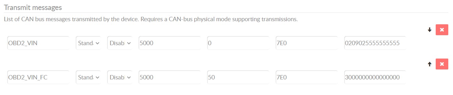
 obd2-transmit-list-example-canedge
Image alt text: Example CANedge configuration showing a transmit list for OBD2 PID requests, demonstrating how to set up specific PID requests for data logging.
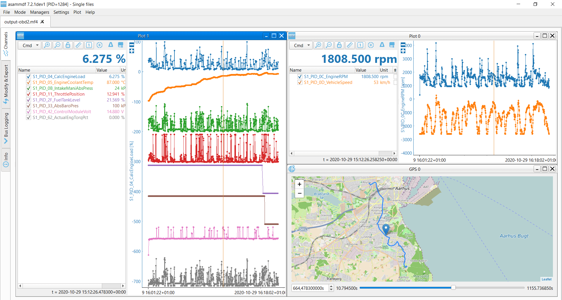 OBD2 data decoded visual plot asammdf CAN bus DBC file
Image alt text: Visual plot of decoded OBD2 data in asammdf, illustrating how CAN bus DBC files can be used to decode and visualize logged OBD2 data for analysis.
Step #3: DBC Decoding of Raw OBD2 Data
For analysis and visualization, raw OBD2 data must be decoded into ‘physical values’ (e.g., km/h, °C). Decoding information is available in ISO 15031-5/SAE J1979 and online resources like Wikipedia. We provide a free OBD2 DBC file to simplify DBC decoding in most CAN bus software tools.
Decoding OBD2 data is more intricate than standard CAN signal decoding because multiple OBD2 PIDs share the same CAN ID (e.g., 0x7E8). Thus, the CAN ID alone isn’t enough to identify the signals within the payload.
To resolve this, both the CAN ID, OBD2 mode, and OBD2 PID must be used for signal identification. This is a form of multiplexing, specifically ‘extended multiplexing‘, which can be implemented in DBC files.
CANedge: Your OBD2 Data Logging Solution
The CANedge offers an easy way to log OBD2 data directly to an 8-32 GB SD card. Simply connect it to your vehicle via the OBD2 connector to start logging, and use free software/APIs and our OBD2 DBC for data decoding.
OBD2 logger intro
CANedge
OBD2 Multi-Frame Communication Examples: ISO-TP in Action
OBD2 communication, governed by ISO-TP (ISO 15765-2), frequently uses multi-frame messages for larger data sets. While earlier examples focused on single-frame exchanges, this section illustrates multi-frame communication.
Multi-frame OBD2 exchanges require flow control frames (see our UDS introduction). A common approach is to transmit a static flow control frame approximately 50 ms after the initial request frame, as demonstrated in the CANedge configuration example.
Analyzing multi-frame OBD2 responses necessitates CAN software/API tools that support ISO-TP, such as the CANedge MF4 decoders.
 OBD2-multi-frame-request-message-vehicle-identification-number
Image alt text: Example of an OBD2 multi-frame request message for Vehicle Identification Number (VIN), showing the structure of a multi-frame request in OBD2 communication.
Example 1: Retrieving Vehicle Identification Number (VIN) via OBD2
The Vehicle Identification Number (VIN) is crucial for telematics, diagnostics, and more (detailed in our UDS introduction). To retrieve the VIN using OBD2, mode 0x09 and PID 0x02 are used:
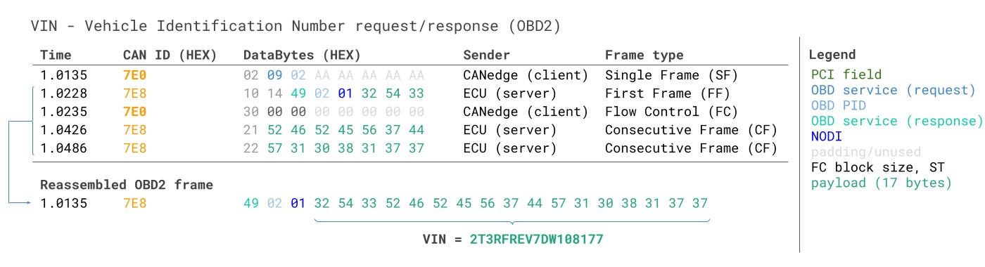 VIN Vehicle Identification Number OBD2 Example multi-frame
The diagnostic tool sends a Single Frame request with PCI field (0x02), request service identifier (0x09), and PID (0x02). The vehicle responds with a First Frame containing the PCI, length (0x014 = 20 bytes), mode (0x49, i.e., 0x09 + 0x40), and PID (0x02). Following the PID is byte 0x01, representing the Number Of Data Items (NODI), which is 1 in this case (refer to ISO 15031-5 / SAE J1979 for details). The subsequent 17 bytes encode the VIN, which can be converted from HEX to ASCII using methods described in our UDS introduction.
Example 2: OBD2 Multi-PID Request (Up to 6 PIDs)
Diagnostic tools can request up to 6 mode 0x01 OBD2 PIDs in a single request frame. The ECU will respond with data for supported PIDs (omitting unsupported ones), potentially using multi-frame responses if necessary.
This method enhances data collection efficiency but complicates signal encoding, making generic OBD2 DBC files less suitable. We generally advise against this approach. Below is an example trace:
 Requesting multiple PIDs in one request
The multi-frame response structure is similar to the VIN example, but the payload includes both the requested PIDs and their corresponding data. The PIDs in the example are ordered similarly to the request order, a common but not strictly standardized practice.
Decoding such responses via generic DBC files is challenging. This method is not recommended for practical data logging unless specialized tools with built-in support are used. It effectively introduces extended multiplexing, with added complexity in payload structure. Creating a generalized DBC file for diverse vehicles with varying supported PIDs becomes very difficult. Furthermore, managing multiple such multi-PID requests and uniquely identifying messages becomes nearly impossible through DBC manipulations alone.
Workarounds could involve custom scripts and recording transmit messages to correlate requests and responses, but these approaches are hard to scale.
Example 3: OBD2 Diagnostic Trouble Codes (DTCs) Retrieval
OBD2 can retrieve emissions-related Diagnostic Trouble Codes (DTCs) using mode 0x03, ‘Show stored Diagnostic Trouble Codes’. No PID is included in the request. Responding ECUs report the number of stored DTCs (potentially zero) and then list each DTC, with each DTC occupying 2 data bytes. Multi-frame responses are necessary when more than 2 DTCs are stored.
The 2-byte DTC value is structured as per ISO 15031-5/ISO 15031-6. The first 2 bits define the ‘category’, and the remaining 14 bits form a 4-digit hexadecimal code, as illustrated. Decoded DTC values can be looked up using OBD2 DTC lookup tools like repairpal.com.
The example below shows a request to an ECU with 6 stored DTCs.
Image alt text: Example of OBD2 DTC (Diagnostic Trouble Code) DBC interpretation, detailing how to decode the 2-byte DTC value to understand the category and code of diagnostic trouble codes.
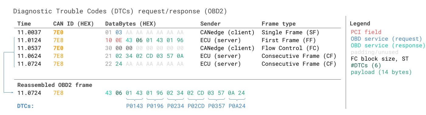 OBD2 Diagnostic Trouble Codes DTC CAN Bus Request Response Example
OBD2 Data Logging: Use Case Examples
OBD2 data logging in cars and light trucks has diverse applications:
Image alt text: Illustration of an OBD2 data logger in a car, representing the use of OBD2 data logging for on-board diagnostics in vehicles.
Vehicle Data Logging
OBD2 data from cars can be leveraged for fuel efficiency improvements, driving behavior analysis, prototype component testing, and insurance telematics.
obd2 logger
Image alt text: Graphic depicting OBD2 real-time streaming diagnostics via USB, showcasing the use of OBD2 interfaces for live vehicle data analysis and diagnostics.
Real-Time Vehicle Diagnostics
OBD2 interfaces enable real-time streaming of human-readable OBD2 data, crucial for diagnosing vehicle issues on the fly.
obd2 streaming
Image alt text: Visual representing OBD2 data logging for predictive maintenance, highlighting the use of OBD2 data and IoT for predicting and preventing vehicle breakdowns.
Predictive Maintenance
Cars and light trucks can be remotely monitored via IoT-enabled OBD2 loggers to predict and prevent potential breakdowns.
predictive maintenance
Image alt text: Illustration of a black box CAN logger, representing the use of OBD2 loggers as vehicle ‘black boxes’ for insurance, warranty, and diagnostic purposes.
Vehicle Black Box Logging
An OBD2 logger can serve as a ‘black box’ for vehicles or equipment, providing crucial data for dispute resolution or in-depth diagnostics.
can bus blackbox
Do you have an OBD2 data logging application in mind? Contact us for a free consultation!
Contact us
Explore our guides section for more introductory materials, or download our ‘Ultimate Guide’ PDF.
Need to log or stream OBD2 data?
Get your OBD2 data logger today!
Buy now
Contact us
Recommended for you
OBD2 DATA LOGGER: EASILY LOG & CONVERT OBD2 DATA
 CANedge2 – Dual CAN Bus Telematics Dongle
CANEDGE2 – PRO CAN IoT LOGGER
CAN BUS INTERFACE: STREAMING OBD2 DATA WITH SAVVYCAN