For automotive enthusiasts and DIY mechanics, having the right tools for diagnostics is essential. Sometimes, off-the-shelf solutions don’t quite meet specific needs, and that’s where creating custom components becomes invaluable. This guide will walk you through the process of building your own OBD2 connector, allowing for tailored diagnostic setups or specific project requirements. Please remember, while this guide provides steps for creating an OBD2 connector, working with vehicle electronics requires caution. Ensure you have a basic understanding of automotive wiring and proceed at your own risk.
Essential Tools and Components
Before diving into the build, gather the necessary tools and parts. Having everything ready will streamline the process and ensure a smoother experience.
- Wire Strippers/Cutters: For preparing wires by removing insulation and cutting them to the desired length.
- Needle-nose Pliers: Useful for manipulating small components, especially when working with connector pins.
- Molex Crimping Tool (Recommended): Although not strictly required, a crimping tool ensures secure and professional connections between wires and connector pins. This is highly recommended for reliability.
- Soldering Iron (Recommended): Soldering provides a robust and electrically sound connection, especially for fine wires. While crimping can be sufficient, soldering enhances durability.
- 4-Pin Connector: This connector will interface with your custom wiring. Ensure it’s compatible with your intended application. A reliable option is the Corsa Technic 4-pin connector, designed for 22-16AWG wire and 1.3-1.7mm insulation.
- OBD-II Cable: This cable provides the OBD2 connector interface. The Corsa Technic OBD-II Cable is a suitable choice, providing a standard OBD2 connector with pre-attached wires.
For cost-saving, if you have spare automotive wiring available, you can purchase just the female OBD-II connector and run individual wires to your 4-pin connector. However, ensure your wire gauge is compatible with the chosen 4-pin connector pins.
Understanding OBD2 Connector Pinout for Custom Builds
The standard OBD2 connector has 16 pins, but for many custom diagnostic applications, only a few are necessary. In this guide, we will focus on utilizing four key pins:
- Pin 4 (Chassis Ground): Provides the ground reference for the vehicle’s electrical system. In the specified OBD-II cable (OBD2C), this is an orange wire.
- Pin 6 (CAN [J-2284] High): Carries the CAN bus high signal, crucial for communication in modern vehicles. This is the green wire on the OBD2C.
- Pin 14 (CAN [J-2284] Low): Carries the CAN bus low signal, working in tandem with CAN High for data transmission. This is the brown wire with a white stripe on the OBD2C.
- Pin 16 (Battery Power): Supplies battery voltage to the diagnostic tool via the OBD2 connector. This is the green wire with a white stripe on the OBD2C.
These four pins are fundamental for establishing a CAN bus communication link through your custom OBD2 connector, which is often used for basic diagnostics and data retrieval.
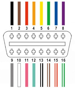 OBD2 connector pinout highlighting pins 4, 6, 14, and 16
Step-by-Step Guide to Building Your Custom OBD2 Connector Harness
Let’s proceed with the construction of your custom OBD2 connector harness.
Step 1: Preparing the OBD-II Cable Wires
Begin by preparing the wires from the OBD-II cable. It’s often recommended to twist pairs of wires for signal integrity, especially in CAN bus systems.
- Remove the outer sheath and shielding from the OBD-II cable to access the individual wires.
- Carefully separate the four wires you will be using (pins 4, 6, 14, and 16 as listed above).
- Organize the remaining 12 wires and secure them out of the way using a zip tie or electrical tape to keep your workspace tidy.
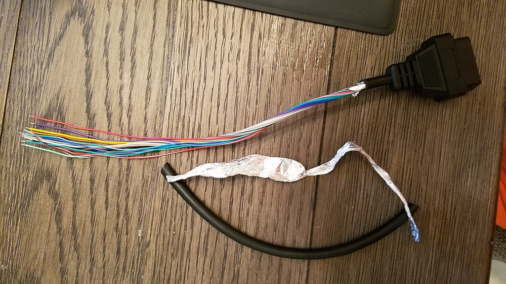 Stripped OBD2 cable sheath revealing internal wires
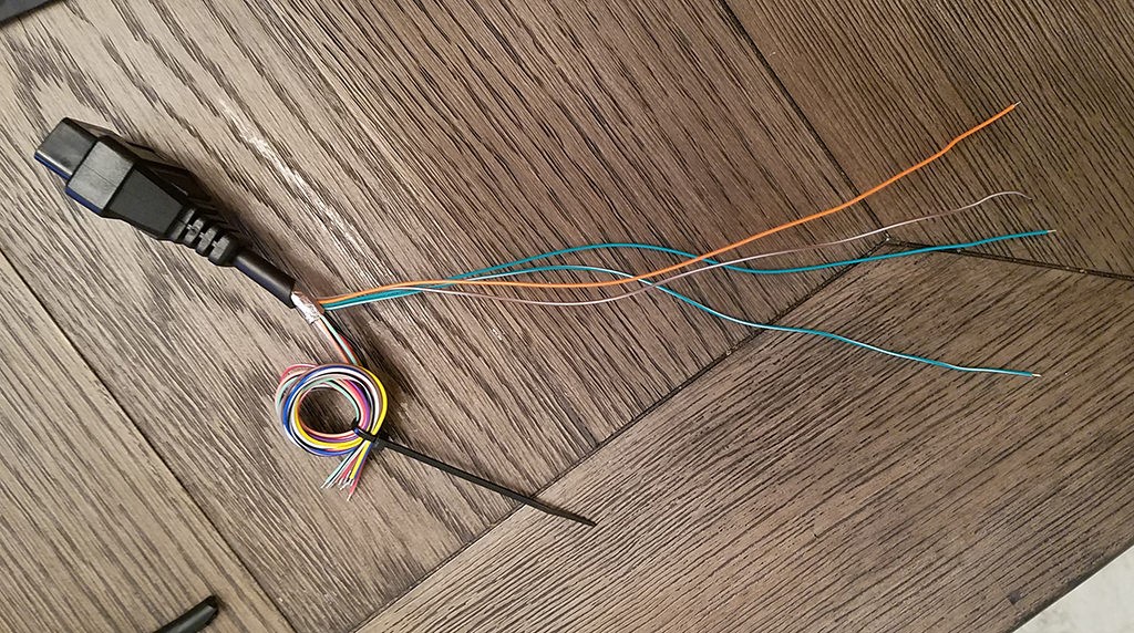 Separated wires from the OBD2 cable for custom connector assembly
Step 2: Preparing the Wires for the 4-Pin Connector
The wires in the specified OBD-II cable (OBD2C) are 26AWG, which is finer than the 22AWG minimum recommended for the 4-pin connector pins (4PC). To ensure a secure connection, we’ll thicken the wire ends.
- The OBD2C wires come pre-stripped with approximately 1/8″ of exposed wire. Strip an additional 1/4″ to get about 3/8″ of exposed wire.
- Fold the exposed wire over itself to double its thickness.
- Twist the folded wire to create a more substantial end that will fit better within the 4-pin connector pin.
- Slide one of the provided rubber seals from the 4-pin connector kit onto each of the four prepared wires. These seals provide environmental protection at the connector.
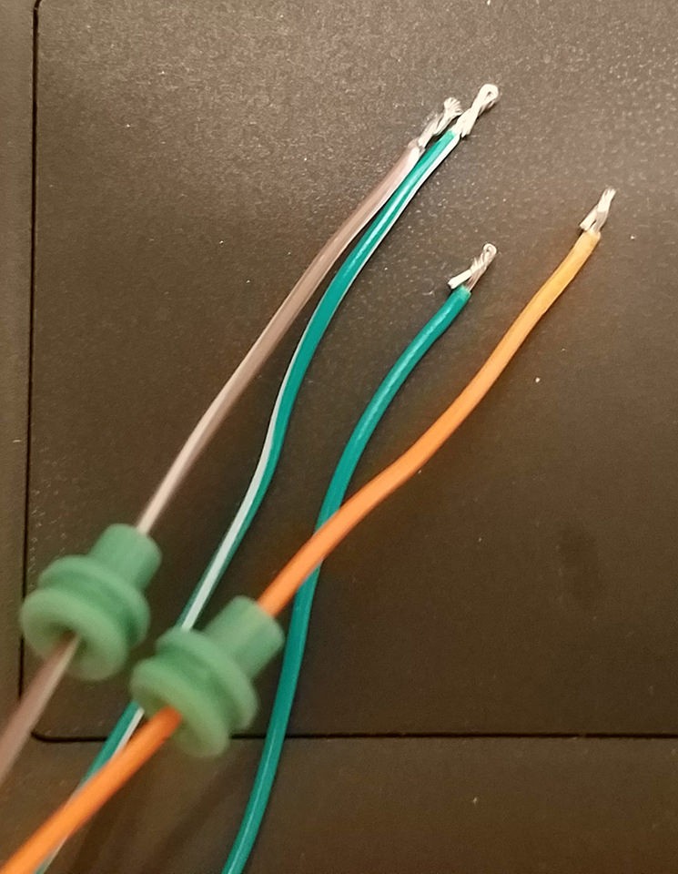 Preparing OBD2 cable wires by folding and twisting to increase thickness for better pin connection
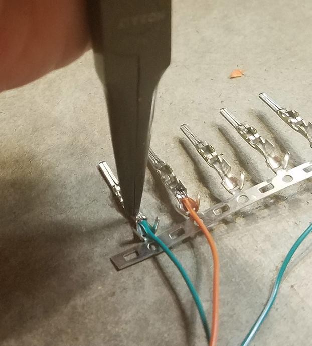
Step 3: Attaching Pins to the Wires
Now, attach the pins to the prepared wire ends.
- Observe the 4-pin connector pins. They have two sets of prongs: one to crimp onto the wire and another to crimp onto the rubber seal.
- Insert the prepared wire into the pin, ensuring the exposed wire aligns with the front prongs (the ones closer to the pin tip).
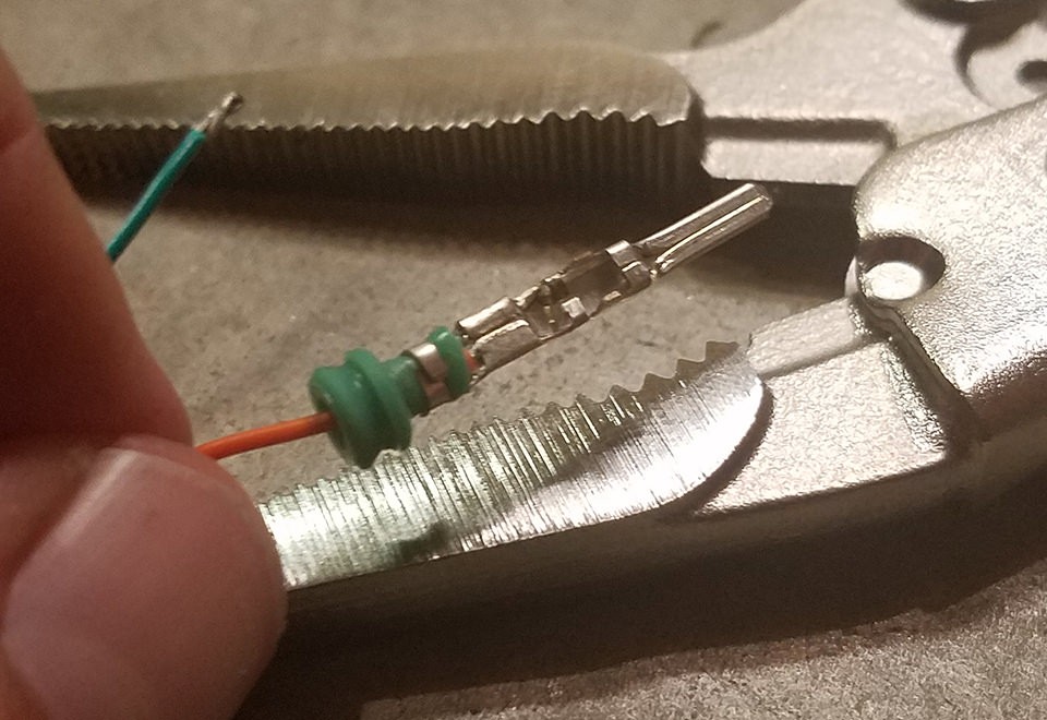
- Use needle-nose pliers to hold the wire in place during the next step, as the wire is quite thin compared to the pin.
 Close-up showing the thin OBD2 wire inserted into the larger 4-pin connector pin before crimping or soldering
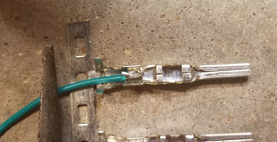
Step 4: Soldering the Wires to the Pins (Recommended)
Soldering is highly recommended for a reliable connection, especially with the fine wires.
- Carefully solder the wire to the pin connector. Ensure the solder creates a solid electrical and mechanical connection.
- Allow the solder joint to cool before proceeding to the next step.
Safety Tip: If you are new to soldering, practice on scrap wires first. Ensure you work in a well-ventilated area and use appropriate safety equipment.
 Soldering the OBD2 wire to the connector pin for a robust connection
Step 5: Crimping the Wire Prongs (Alternative to Soldering)
If you prefer crimping, or do not have soldering equipment, use a crimping tool for this step.
- If using a Molex crimping tool, use the appropriate setting for the pin and wire gauge to crimp the front prongs securely around the wire.
- If using needle-nose pliers as an alternative, carefully fold one prong at a time over the wire, ensuring a tight crimp.
 Crimping the connector pin prongs around the wire using pliers
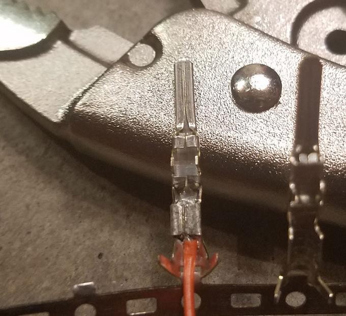 Crimped wire prongs on the connector pin
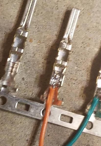
Step 6: Crimping the Seal Prongs
After securing the wire, crimp the rear prongs over the rubber seal to provide strain relief and environmental protection.
- Slide the rubber seal up so it sits between the rear prongs of the connector pin.
- Using a crimping tool or needle-nose pliers, fold the rear prongs over the seal to secure it in place.
 Positioning the rubber seal before crimping the rear prongs
 Crimping the rear prongs over the rubber seal for strain relief and environmental protection
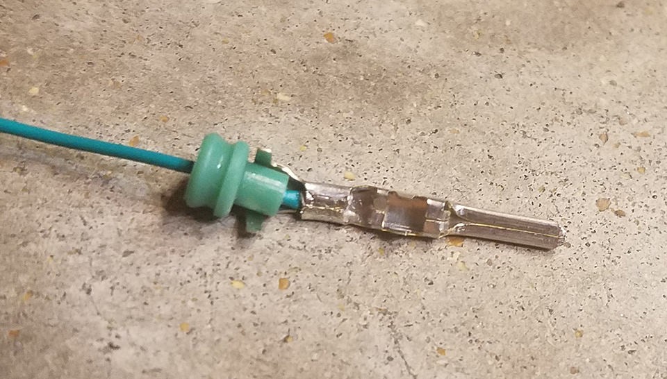
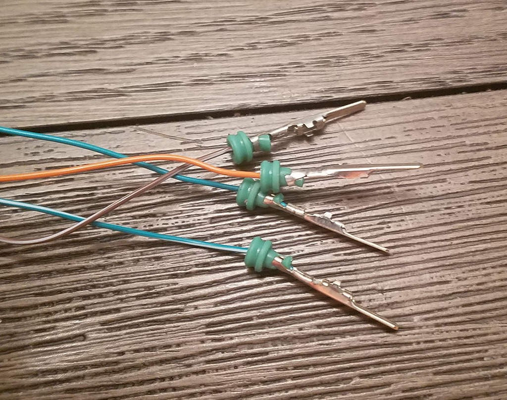 Completed pin with wire and seal attached
Step 7: Wire Pairing (Recommended for CAN Bus)
For CAN bus applications, twisting wire pairs is recommended to reduce electromagnetic interference.
- Pair the wires as follows:
- Pin 4 (orange) / Pin 16 (green w/white stripe) – Power and Ground pair
- Pin 6 (green) / Pin 14 (brown w/white stripe) – CAN High and CAN Low pair
- Twist each pair of wires together.
Step 8: Inserting Pins into the 4-Pin Connector Housing
Finally, insert the pinned wires into the 4-pin connector housing in the correct orientation.
-
Refer to the 4-pin connector diagram and insert the pins into the corresponding slots:
- Pin 14 (brown w/white stripe – CAN Low) > Connector Slot A
- Pin 6 (green – CAN High) > Connector Slot B
- Pin 16 (green w/white stripe – Battery Power) > Connector Slot C
- Pin 4 (orange – Chassis Ground) > Connector Slot D
-
Push each pin into the connector housing from the rear until you hear an audible click, indicating it is locked in place. You may use needle-nose pliers to gently pull the wire from the front to ensure it is securely seated.
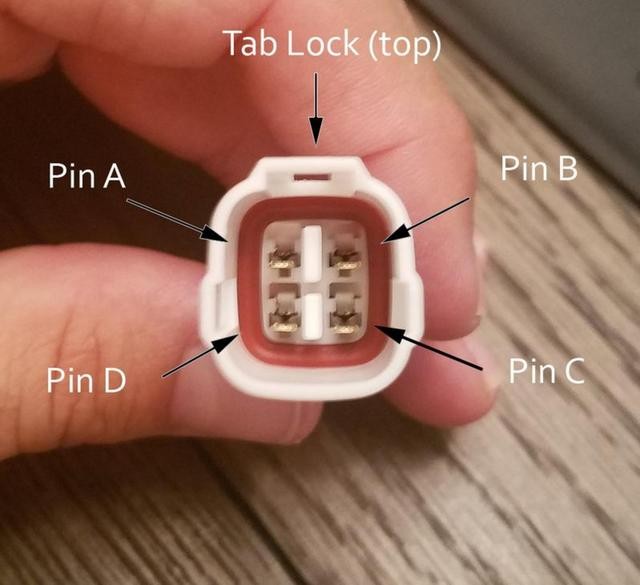 4-Pin connector pin insertion diagram
Completion and Testing
Congratulations! You have now built your custom OBD2 connector harness.
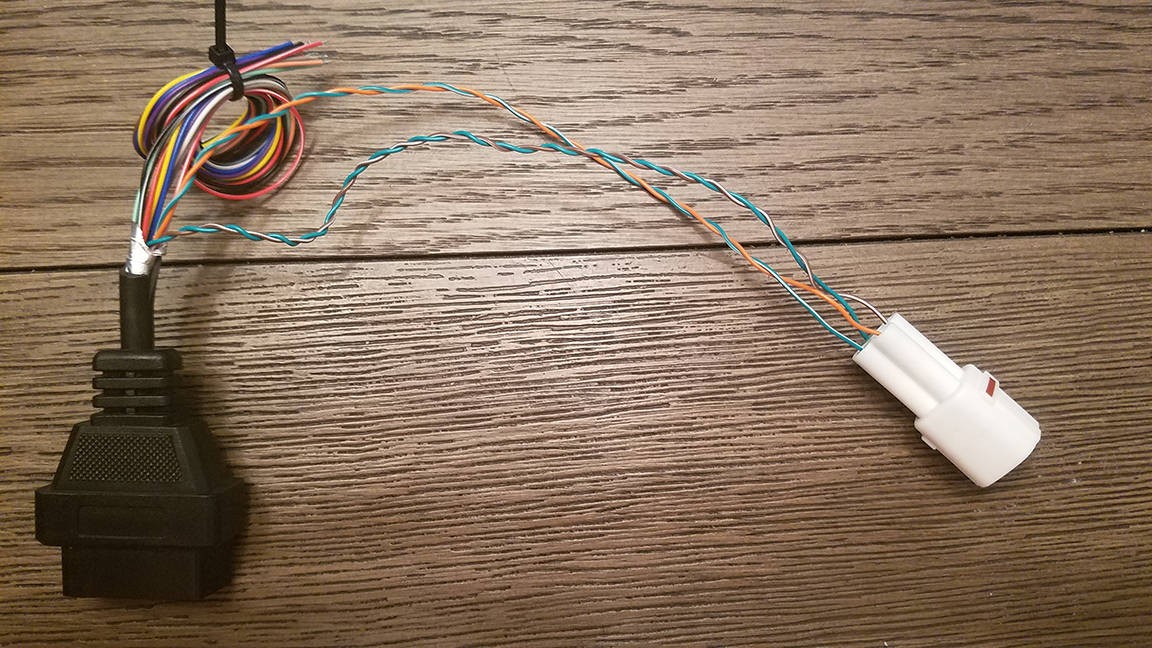 Completed custom OBD2 connector harness
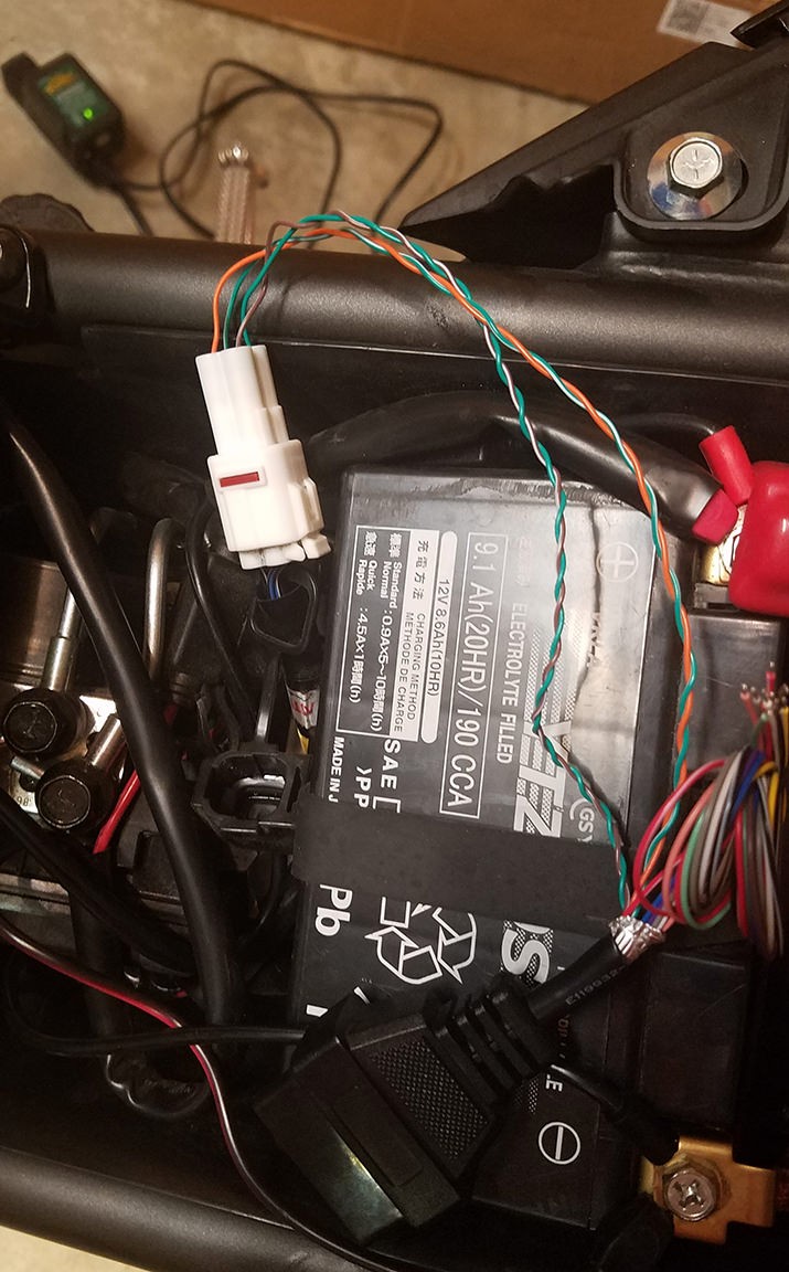 Custom OBD2 connector connected for diagnostics
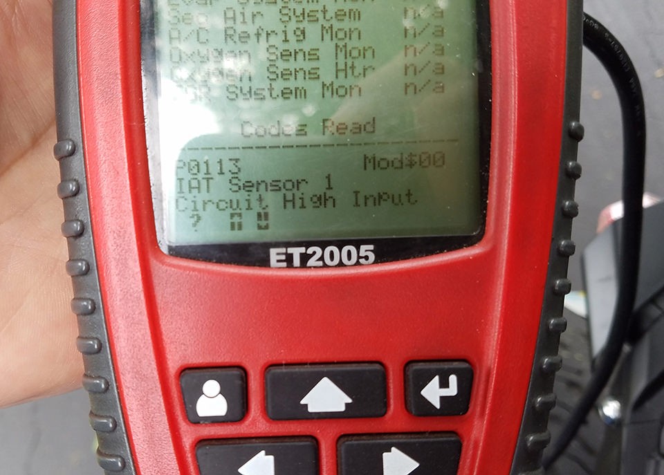 Successful OBD2 diagnostic check
This custom OBD2 connector can now be used for your specific diagnostic or automotive electronics projects. Always double-check your wiring and pinouts before connecting to your vehicle’s OBD2 port. If you encounter any issues or have questions, consult automotive wiring diagrams and seek advice from experienced professionals. Enjoy the enhanced diagnostic capabilities your custom OBD2 connector provides!