Looking for a straightforward and in-depth explanation of Obd2?
This guide offers a comprehensive introduction to the On-Board Diagnostics 2 (OBD2) protocol, covering everything from the OBD2 connector and Parameter IDs (PIDs) to its connection with the CAN bus.
More than just an introduction, this is a practical guide that will teach you how to request and interpret OBD2 data, explore key use cases for data logging, and provide essential tips for working with OBD2 systems.
Discover why this article has become a leading resource for understanding OBD2.
You can also watch our introductory video on OBD2 above – or download this guide as a PDF.
Article Contents:
Author: Martin Falch (Updated January 2025)
 PDF icon
Download as PDF
Understanding OBD2: What is It?
OBD2, or On-Board Diagnostics version 2, is essentially your vehicle’s internal health monitoring system. It’s a standardized protocol that allows access to crucial information, including diagnostic trouble codes (DTCs) and real-time vehicle data, all through the OBD2 connector.
You’ve likely already encountered OBD2 in action, perhaps without even realizing it.
Ever seen the check engine light illuminate on your dashboard?
That light is your car signaling that it has detected a problem. When you take your vehicle to a mechanic, they use an OBD2 scanner to pinpoint the issue.
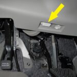
The process involves connecting an OBD2 reader to the OBD2 16-pin connector, usually located near the steering wheel. This tool sends ‘OBD2 requests’ to the vehicle’s computer, and the car responds with ‘OBD2 responses’. These responses can contain a wealth of information, from vehicle speed and fuel levels to detailed Diagnostic Trouble Codes (DTCs). This data allows mechanics to diagnose problems more efficiently and effectively.
Understanding OBD2: A visual representation of the Malfunction Indicator Light (MIL) and an OBD2 scan tool, highlighting the core components of on-board diagnostics.
Is My Car OBD2 Compliant? Checking for OBD2 Compatibility
The question on many minds is: Does my car actually support OBD2?
The good news is, for most modern, non-electric vehicles, the answer is almost certainly yes! Most of these vehicles also operate on the CAN bus network. However, for older vehicles, the presence of a 16-pin OBD2 connector doesn’t guarantee OBD2 support. As ScanTool.net explains, just having the connector isn’t enough.
A reliable way to determine OBD2 compliance is to consider where and when your car was originally purchased:
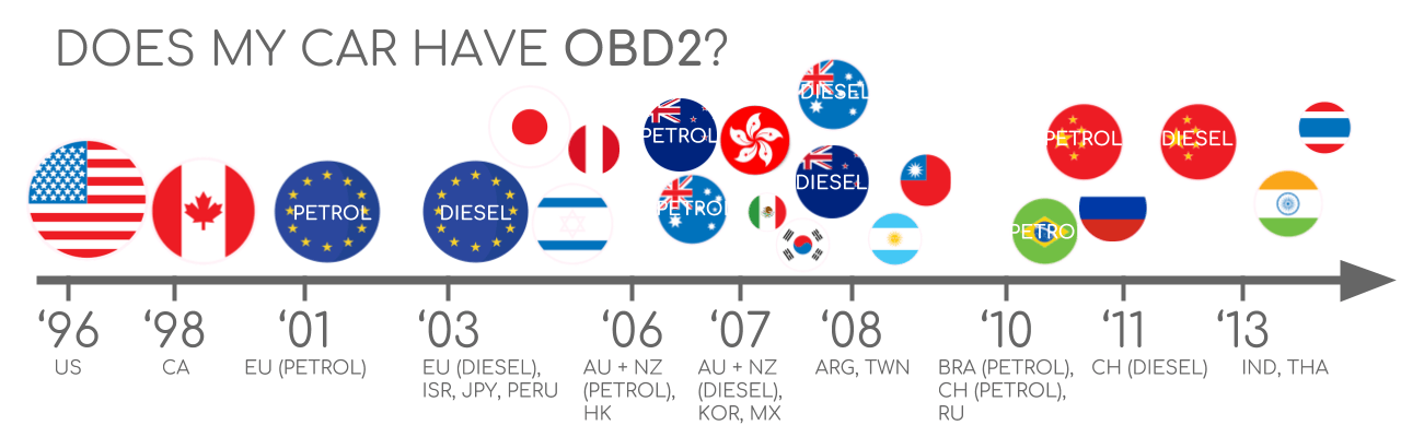 Does My Car Have OBD2?
OBD2 Compliance Guide: A helpful chart illustrating OBD2 compliance by region and vehicle type (EU, US, CAN) with timelines for gasoline and diesel vehicles.
A Look at OBD2 History and Evolution
The origins of OBD2 can be traced back to California. The California Air Resources Board (CARB) mandated the inclusion of OBD systems in all new vehicles starting from 1991 for emission control purposes.
The OBD2 standard we recognize today was largely shaped by recommendations from the Society of Automotive Engineers (SAE). They standardized Diagnostic Trouble Codes (DTCs) and the physical OBD connector across different vehicle manufacturers through the SAE J1962 standard (SAE J1962).
The implementation of OBD2 was a phased process, rolled out progressively across different regions and vehicle types:
- 1996: OBD2 became mandatory in the USA for cars and light trucks.
- 2001: The European Union (EU) mandated OBD2 for gasoline cars.
- 2003: EU extended the requirement to diesel cars as well (referred to as EOBD – European On-Board Diagnostics).
- 2005: OBD2 became mandatory in the US for medium-duty vehicles.
- 2008: US regulations required vehicles to use ISO 15765-4 (CAN) as the foundation for OBD2 communication.
- 2010: OBD2 compliance was finally extended to heavy-duty vehicles in the US.
OBD2 History Infographic: A visual timeline highlighting key milestones in OBD2 history, emphasizing its evolution from emission control to broader vehicle diagnostics.
OBD2 Timeline Graphic: A clear timeline summarizing the historical progression of OBD2 mandates and technological advancements.
OBD3 Future Concept: An image illustrating the potential future of OBD3 with remote diagnostics, emissions testing, cloud connectivity, and IoT integration.
The Future of OBD2: Trends and Predictions
OBD2 is firmly established as a diagnostic standard, but its future form is evolving. Let’s explore some significant trends shaping the future of OBD2:
Originally, legislated OBD2 was primarily designed for emissions control and testing. Interestingly, this means electric vehicles (EVs) aren’t necessarily required to support OBD2 in its traditional form. In fact, very few modern EVs support standard OBD2 requests. Instead, many rely on OEM-specific UDS (Unified Diagnostic Services) communication protocols. This often makes it challenging to access data from EVs unless the proprietary communication rules have been reverse-engineered. However, there are successful cases of reverse engineering efforts, as seen in studies for electric car brands like Tesla, Hyundai/Kia, Nissan, and VW/Skoda EVs.
Today’s OBD2 implementations vary in data richness and underlying communication protocols. To address these limitations, modern alternatives are emerging, such as WWH-OBD (World Wide Harmonized OBD) and OBDonUDS (OBD on UDS). Both aim to enhance and streamline OBD communication by utilizing the UDS protocol as a foundation. For a deeper understanding of these protocols, our introduction to UDS offers valuable insights.
In our increasingly connected world, traditional OBD2 testing methods can seem inefficient. Manually performing emission control checks is time-consuming and costly.
The proposed solution? OBD3 – integrating telematics into all vehicles.
OBD3 envisions equipping all cars with a small radio transponder, similar to those used for bridge tolls. This would allow vehicles to transmit their Vehicle Identification Number (VIN) (vehicle identification number) and DTCs wirelessly via WiFi to a central server for automated checks.
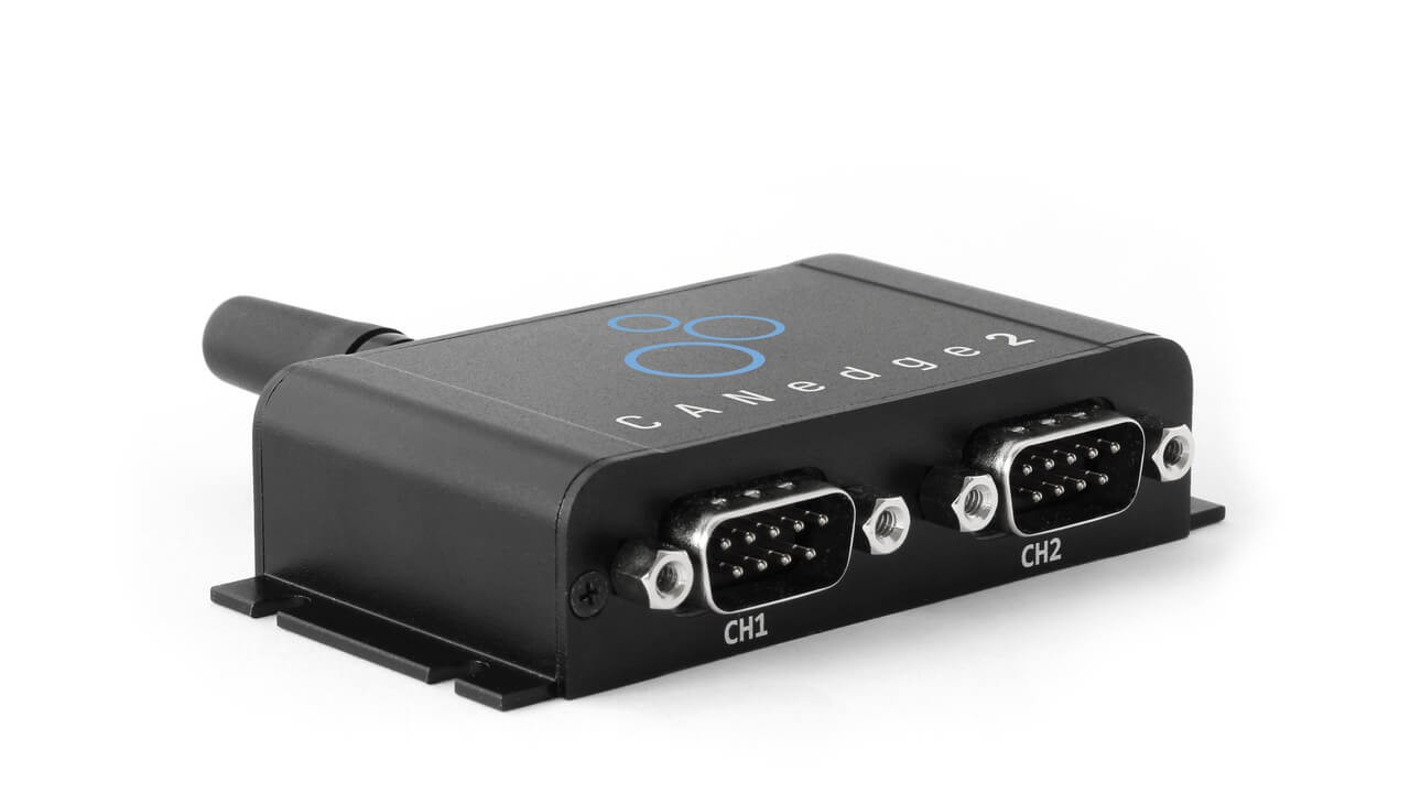
Many devices already exist that facilitate data transfer from CAN or OBD2 via WiFi or cellular networks. Examples include the CANedge2 WiFi CAN logger and the CANedge3 3G/4G CAN logger.
While OBD3 offers cost savings and convenience, it also raises political and privacy concerns related to surveillance.
The original purpose of OBD2 was for stationary emission controls in repair shops.
However, OBD2 is now extensively utilized by third parties for real-time data generation through OBD2 dongles, CAN loggers, and similar devices. Interestingly, the German car industry is advocating for changes that could significantly impact this trend:
“OBD has been designed to service cars in repair shops. In no way has it been intended to allow third parties to build a form of data-driven economy on the access through this interface“
– Christoph Grote, SVP Electronics, BMW (2017)
The proposal suggests “disabling” OBD2 functionality while driving and instead centralizing data collection through manufacturer servers. This would effectively give manufacturers control over the valuable realm of ‘automotive big data’.
The rationale often cited is security, aiming to mitigate the risk of car hacking. However, many observers view this as a commercially motivated move. Whether this trend gains momentum remains to be seen, but it has the potential to disrupt the market for third-party OBD2 services.
OBD2 Data Access Challenges in EVs: A conceptual image depicting an OBD2 connector being removed from an electric vehicle, symbolizing the restricted data access in EVs.
Enhance Your CAN Bus Expertise
Want to become a CAN bus expert and deepen your understanding of OBD2’s underlying network?
Our comprehensive ‘Ultimate CAN Guide’ compiles 12 ‘simple intros’ into a single 160+ page PDF:
Download now
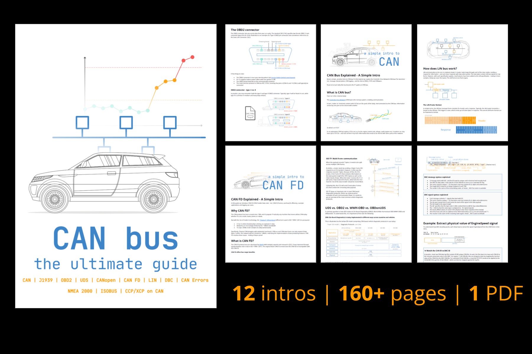 CAN Bus – The Ultimate Guide Tutorial PDF
Decoding OBD2 Standards: Connector, Protocols, and PIDs
On-board diagnostics, or OBD2, functions as a higher-layer protocol, similar to a language, that operates on a communication method like CAN (Controller Area Network), which is akin to a phone line. This positions OBD2 alongside other CAN-based higher-layer protocols such as J1939, CANopen, and NMEA 2000.
Specifically, OBD2 standards define the physical OBD2 connector, the lower-layer communication protocols, OBD2 Parameter IDs (PIDs), and other critical aspects.
These standards can be visualized using the 7-layer OSI (Open Systems Interconnection) model. In the following sections, we will focus on the most relevant standards within this model.
In the OSI model overview, it’s important to note that standards from both SAE (primarily US-focused) and ISO (international) cover various layers. Many of these standards are technically very similar, for instance, SAE J1979 and ISO 15031-5, or SAE J1962 and ISO 15031-3.
OBD2 and CAN Bus in OSI Model: A diagram placing OBD2 and CAN bus within the 7-layer OSI model, illustrating the relevant ISO and SAE standards at different layers.
OBD2 Connector Pinout Diagram: A detailed pinout diagram of a Type A OBD2 connector socket (female), highlighting pin assignments for various functions and communication protocols.
The OBD2 Connector: SAE J1962 Standard
The 16-pin OBD2 connector is your gateway to accessing vehicle data. It’s standardized under SAE J1962 (SAE J1962) and ISO 15031-3. It’s also known as the Data Link Connector (DLC).
The illustration above shows a typical Type A OBD2 pin connector.
Here are some key points about the OBD2 connector:
- You’ll typically find the connector near the steering wheel, but it might be concealed in some vehicles.
- Pin 16 provides battery power, often remaining active even when the ignition is off.
- The specific OBD2 pinout configuration is determined by the communication protocol used by the vehicle.
- CAN bus is the most prevalent lower-layer protocol, meaning pins 6 (CAN-H) and 14 (CAN-L) are usually connected.
OBD2 Connector Types: A vs. B
In practice, you may encounter both Type A and Type B OBD2 connectors. Type A is generally found in cars, while Type B is more common in medium and heavy-duty vehicles.
As shown in the illustration, both types share similar pinouts, but they differ in power supply output: Type A provides 12V, while Type B supplies 24V. Baud rates can also vary, with cars typically using 500K and heavy-duty vehicles often using 250K (though 500K support is increasing in heavier vehicles).
A key physical difference is that the Type B OBD2 connector has an interrupted groove in the center. This means a Type B OBD2 adapter cable will be compatible with both Type A and Type B sockets, while a Type A adapter will only fit into a Type A socket.
OBD2 Connector Types A and B: A comparative diagram of OBD2 Connector Type A and Type B, highlighting differences in voltage (12V vs 24V) and physical keying to differentiate between car and truck applications.
OBD2 and CAN Bus Relationship: An illustration clarifying the relationship between OBD2 as a protocol and CAN bus as the underlying communication network, emphasizing ISO 15765 standards.
OBD2 and CAN Bus Integration: ISO 15765-4 Explained
Since 2008, CAN bus has been mandated as the primary lower-layer protocol for OBD2 in all vehicles sold in the US, as per ISO 15765.
ISO 15765-4, also known as Diagnostics over CAN (DoCAN), specifies a set of rules and restrictions applied to the CAN standard (ISO 11898) for diagnostic communication.
Specifically, ISO 15765-4 standardizes the CAN interface for diagnostic equipment, focusing on the physical, data link, and network layers:
- CAN bus bit rate must be either 250K or 500K.
- CAN IDs can be 11-bit or 29-bit.
- Specific CAN IDs are designated for OBD requests and responses.
- Diagnostic CAN frame data length is fixed at 8 bytes.
- The OBD2 adapter cable is limited to a maximum length of 5 meters.
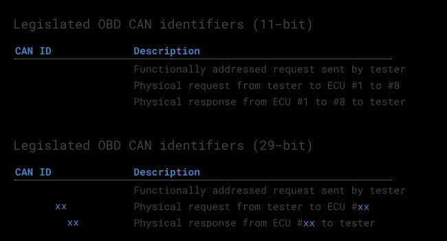
OBD2 CAN Identifiers: 11-bit and 29-bit
All OBD2 communication relies on a request-response messaging system.
In most passenger cars, 11-bit CAN IDs are used for OBD2 communication. The ‘Functional Addressing’ ID, 0x7DF, is used to query all OBD2-compatible Electronic Control Units (ECUs) to see if they have data to report for the requested parameter (as defined in ISO 15765-4). In contrast, CAN IDs in the range 0x7E0-0x7E7 can be used for ‘Physical Addressing’ requests, targeting specific ECUs (though this is less common).
ECUs respond using 11-bit IDs in the range 0x7E8-0x7EF. The most common response ID is 0x7E8 (from the Engine Control Module, ECM), followed by 0x7E9 (from the Transmission Control Module, TCM).
In some vehicles, particularly vans and light, medium, and heavy-duty vehicles, extended 29-bit CAN identifiers may be used for OBD2 communication instead of 11-bit IDs.
Here, the ‘Functional Addressing’ CAN ID is 0x18DB33F1.
Responses in 29-bit CAN typically use IDs ranging from 0x18DAF100 to 0x18DAF1FF (common examples being 18DAF110 and 18DAF11E). The response ID is also sometimes represented in ‘J1939 PGN’ format, specifically PGN 0xDA00 (55808), which is designated as ‘Reserved for ISO 15765-2’ in the J1939-71 standard.
OBD2 Request-Response Frame Structure: A diagram illustrating the structure of OBD2 request and response frames, highlighting the roles of Mode, PID (Parameter ID), and data bytes.
 OBD2 OBD CAN bus Identifiers 7DF 7E8 7E0
OBD2 vs Proprietary CAN Data: A comparison highlighting the distinction between standardized OBD2 data and OEM-specific proprietary CAN bus data, emphasizing their parallel existence within a vehicle.
OBD2 vs. OEM Proprietary CAN Protocols
It’s crucial to understand that a vehicle’s Electronic Control Units (ECUs) do not rely on OBD2 for their primary functions. Each Original Equipment Manufacturer (OEM) implements its own proprietary CAN protocols for core vehicle operations. These proprietary CAN protocols are often specific to the vehicle brand, model, and year. Generally, this OEM-specific CAN data is not publicly documented and requires reverse engineering to interpret.
If you connect a CAN bus data logger to your car’s OBD2 connector, you might observe this OEM-specific CAN data, typically broadcast at high rates (1000-2000 frames/second). However, many newer vehicles employ a ‘gateway’ that blocks access to this proprietary CAN data through the OBD2 port, only allowing OBD2 communication.
Think of OBD2 as an ‘add-on’ higher-layer protocol that operates alongside the OEM-specific protocol.
Bit-rate and ID Validation in OBD2
As mentioned, OBD2 can utilize either of two bit rates (250K, 500K) and either of two CAN ID lengths (11-bit, 29-bit). This results in four potential combinations. In modern cars, 500K bit rate and 11-bit IDs are the most common, but external tools should systematically verify this.
ISO 15765-4 provides recommendations for an initialization sequence to determine the correct combination, illustrated in the flowchart below. This method leverages the fact that OBD2-compliant vehicles must respond to a specific mandatory OBD2 request (see the OBD2 PID section for details) and that using an incorrect bit rate will cause CAN error frames.
Newer versions of ISO 15765-4 account for vehicles that may support OBD communication via OBDonUDS rather than OBDonEDS. This article primarily focuses on OBD2/OBDonEDS (OBD on Emission Diagnostic Service as per ISO 15031-5/SAE J1979) as opposed to WWH-OBD/OBDonUDS (OBD on Unified Diagnostic Service as per ISO 14229, ISO 27145-3/SAE J1979-2).
To test for OBDonEDS vs. OBDonUDS, a diagnostic tool may send additional UDS requests with 11-bit/29-bit functional address IDs for service 0x22 and Data Identifier (DID) 0xF810 (protocol identification). Vehicles supporting OBDonUDS should have ECUs that respond to this DID.
In practice, OBDonEDS (also known as OBD2, SAE OBD, EOBD, or ISO OBD) is prevalent in most non-EV cars today, while WWH-OBD is mainly used in EU trucks and buses.
OBD2 Bit-rate and CAN ID Validation Flowchart: A flowchart outlining the process for validating OBD2 bit-rate and CAN ID configurations according to ISO 15765-4, crucial for establishing reliable OBD2 communication.
OBD2 Protocol Stack: A graphic depicting the five lower-layer protocols used in OBD2 standards – CAN (ISO 15765), KWP2000 (ISO 14230-4), ISO 9141, SAE J1850 VPW, and SAE J1850 PWM – illustrating the evolution of OBD2 communication technologies.
Five Lower-Layer OBD2 Protocols
Today, CAN bus (ISO 15765) is the dominant lower-layer protocol for OBD2 in the vast majority of vehicles.
However, when working with older vehicles (pre-2008), it’s helpful to be aware of the other four lower-layer protocols that were used for OBD2. The pinouts of the OBD2 connector can sometimes indicate which protocol a vehicle might be using.
- ISO 15765 (CAN bus): Mandatory in US cars since 2008 and now the most common protocol.
- ISO 14230-4 (KWP2000): Keyword Protocol 2000, widely used in 2003+ vehicles, especially in Asia.
- ISO 9141-2: Used in EU, Chrysler, and Asian cars in the 2000-2004 period.
- SAE J1850 (VPW – Variable Pulse Width Modulation): Predominantly used in older GM vehicles.
- SAE J1850 (PWM – Pulse Width Modulation): Primarily used in older Ford vehicles.
ISO-TP: Transporting OBD2 Messages Beyond 8 Bytes (ISO 15765-2)
All OBD2 data communication over CAN bus is managed by a transport protocol called ISO-TP (ISO 15765-2). This protocol enables the transmission of data payloads exceeding the 8-byte limit of standard CAN frames. This is essential in OBD2 for tasks like retrieving the Vehicle Identification Number (VIN) or Diagnostic Trouble Codes (DTCs), which often require more than 8 bytes of data. ISO 15765-2 handles data segmentation, flow control, and reassembly to facilitate these larger data transfers. For a more detailed explanation, refer to our intro to UDS.
However, much of the time, OBD2 data fits within a single CAN frame. In these cases, ISO 15765-2 specifies the use of a ‘Single Frame’ (SF) format. Here, the first data byte (PCI field – Protocol Control Information) indicates the payload length (excluding padding), leaving 7 bytes available for OBD2-related communication.
ISO-TP Frame Types for OBD2: An illustration of ISO-TP frame types used in OBD2 communication, including Single Frame (SF), First Frame (FF), Consecutive Frame (CF), and Flow Control (FC) frames, as defined in ISO 15765-2.
Dissecting the OBD2 Diagnostic Message: SAE J1979, ISO 15031-5
To fully grasp OBD2 communication over CAN, let’s examine a raw ‘Single Frame’ OBD2 CAN message. In simple terms, an OBD2 message consists of a CAN identifier, a data length indicator (PCI field), and the actual data payload. The payload is structured into Mode, Parameter ID (PID), and data bytes.
OBD2 Message Structure Breakdown: A diagram dissecting the structure of an OBD2 message frame, detailing the positions and roles of CAN ID, PCI field, Mode, PID, and Data Bytes in OBD-II communication.
Example: OBD2 Request and Response Cycle
Before diving into the components of an OBD2 message, let’s consider a practical example: requesting and receiving ‘Vehicle Speed’.
In this scenario, an external diagnostic tool sends a request message to the vehicle with CAN ID 0x7DF and a 2-byte payload: Mode 0x01 and PID 0x0D. The vehicle responds with a message using CAN ID 0x7E8 and a 3-byte payload. This payload includes the vehicle speed value in the 4th byte, which is 0x32 (50 in decimal).
By consulting the OBD2 PID specifications for PID 0x0D, we can determine that this value, 50, represents a physical value of 50 km/h (kilometers per hour).
Next, we will explore the OBD2 modes and PIDs in more detail.
OBD2 Request-Response Example (7DF-7E8): A sequence diagram illustrating an OBD2 request for Vehicle Speed (PID 0x0D) using CAN ID 0x7DF and the corresponding response with Vehicle Speed data via CAN ID 0x7E8.
OBD2 PID 0x0D Example: A detailed example focusing on OBD2 PID 0x0D (Vehicle Speed), showing the request frame (Mode 01, PID 0D) and the interpretation of the response frame data.
OBD2 Service Modes Overview: A chart listing the 10 standard OBD2 service modes (or modes), including Mode 01 (Show current data), Mode 02 (Show freeze frame data), Mode 03 (Show stored DTCs), and others, providing a high-level view of OBD2 diagnostic capabilities.
The 10 OBD2 Services (Modes)
There are 10 standardized OBD2 diagnostic services, often referred to as modes. Mode 0x01 is used to access current, real-time data, while other modes are used to retrieve and clear Diagnostic Trouble Codes (DTCs), access freeze frame data, and perform other diagnostic functions.
It’s important to note that vehicles are not required to support all 10 OBD2 modes. Additionally, manufacturers may implement OEM-specific OBD2 modes beyond the standardized set.
In OBD2 messages, the mode is indicated in the second byte of the data payload. In a request message, the mode is included directly (e.g., 0x01). In a response message, 0x40 is added to the requested mode (e.g., a response to mode 0x01 will start with 0x41).
OBD2 Parameter IDs (PIDs)
Within each OBD2 mode, there are Parameter IDs (PIDs).
For instance, Mode 0x01 contains approximately 200 standardized PIDs that provide real-time data on parameters such as vehicle speed, engine RPM, and fuel level. However, a vehicle doesn’t necessarily support all PIDs within a given mode. In practice, most vehicles only support a subset of the available PIDs.
One PID holds special significance:
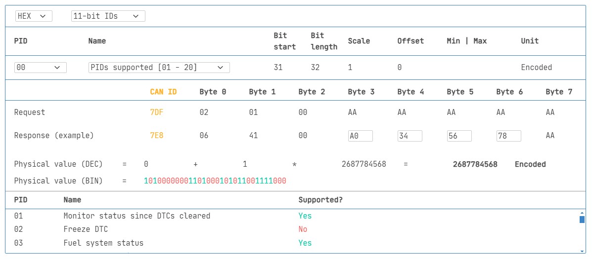
If an emissions-related ECU supports any OBD2 services at all, it must support Mode 0x01 PID 0x00. When queried with PID 0x00, the vehicle ECU responds to indicate its support for PIDs 0x01-0x20. This makes PID 0x00 a fundamental ‘OBD2 compatibility test’. Furthermore, PIDs 0x20, 0x40, 0x60, 0x80, 0xA0, and 0xC0 can be used to determine support for the remaining PIDs within Mode 0x01 in blocks of 32 PIDs each.
OBD2 Request-Response with PIDs: Reiteration of the OBD2 request-response structure, emphasizing the role of PIDs in specifying the data parameters being requested and returned.
 OBD2 PID overview tool
OBD2 PID Overview Tool Screenshot: A screenshot of an OBD2 PID overview tool, showcasing its interface and functionality for exploring and understanding OBD2 Parameter IDs (PIDs) within Service 01.
Tip: Using an OBD2 PID Overview Tool
The appendices of SAE J1979 and ISO 15031-5 contain scaling information for standard OBD2 PIDs, which is essential for converting raw data bytes into meaningful physical values (as explained in our CAN bus introduction).
If you need to quickly look up details for a Mode 0x01 PID, our OBD2 PID overview tool is a helpful resource. This tool aids in constructing OBD2 request frames and dynamically decoding OBD2 responses.
OBD2 PID overview tool
Practical Guide: Logging and Decoding OBD2 Data
In this section, we’ll walk through a practical example of how to log OBD2 data using the CANedge CAN bus data logger.
The CANedge allows you to configure custom CAN frames for transmission, making it ideal for OBD2 logging.
Once configured, you can easily connect the CANedge to your vehicle using our OBD2-DB9 adapter cable.
OBD2 Data Logger Setup: A diagram illustrating an OBD2 data logger connected to a vehicle’s OBD2 port, highlighting the request (7DF) and response (7E8) CAN IDs used in OBD2 data logging.
 OBD2 bit rate test Verifying OBD2 Bit Rate: A screenshot showing a successful CAN frame transmission at 500K, demonstrating the bit rate validation step in setting up OBD2 communication.
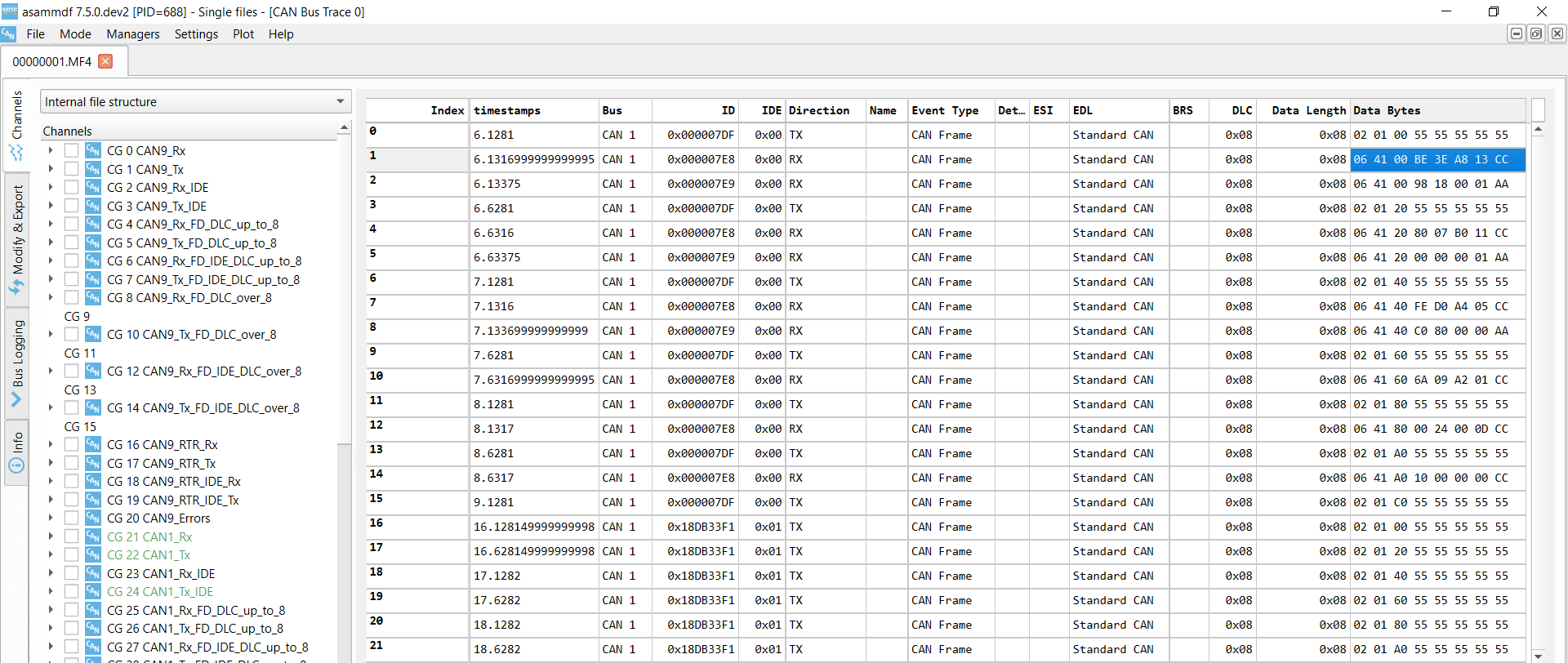 OBD2 Supported PIDs Test Supported PIDs Test in asammdf: A screenshot from asammdf software showing responses to ‘Supported PIDs’ requests, used to identify which OBD2 PIDs are supported by the vehicle.
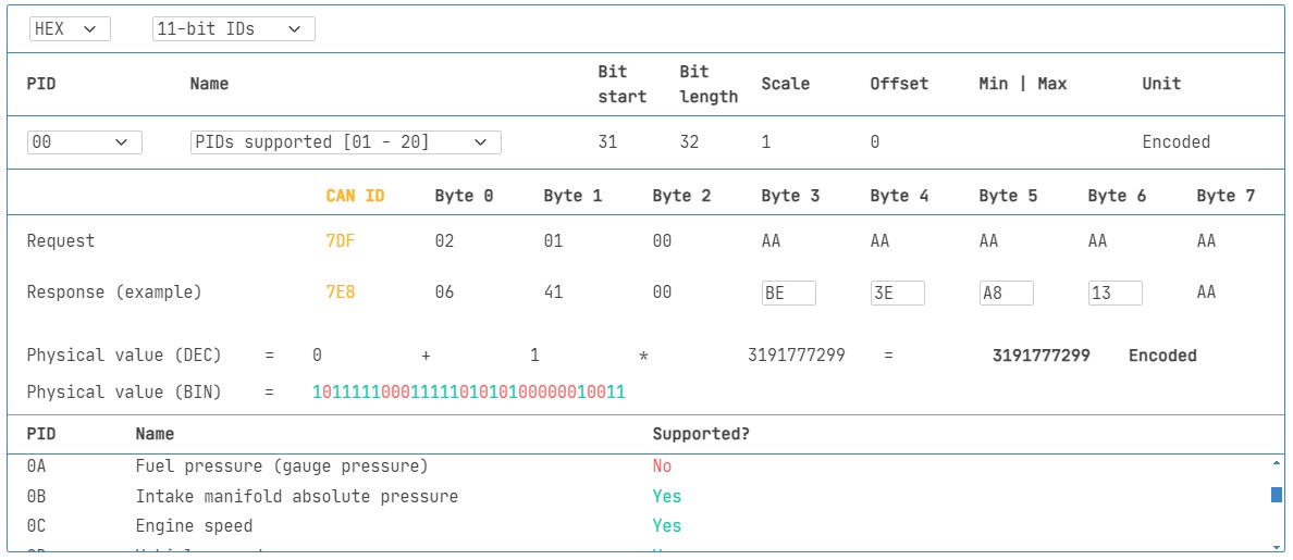 Review supported PIDs via OBD2 lookup tool
Step #1: Validate Bit-rate, CAN IDs, and Supported PIDs
As discussed earlier, ISO 15765-4 outlines how to determine the correct bit rate and CAN IDs for a specific vehicle. You can use the CANedge to perform these tests as follows (refer to the CANedge Intro for detailed instructions):
- Test Bit Rate: Send a CAN frame at 500K and check for successful transmission. If unsuccessful, try 250K.
- Set Bit Rate: Use the validated bit rate for all subsequent communication.
- Request Supported PIDs: Send multiple ‘Supported PIDs’ requests (Mode 0x01 PID 0x00 and subsequent PIDs to cover the full range) and analyze the responses.
- Determine CAN ID Type: Based on the response IDs (0x7E8-0x7EF for 11-bit or 0x18DAF1xx for 29-bit), determine whether the vehicle uses 11-bit or 29-bit CAN IDs for OBD2.
- Identify Supported PIDs: Analyze the response data to see which PIDs are supported by the vehicle’s ECUs.
We provide pre-configured settings to simplify these initial tests.
Most non-EV cars manufactured in 2008 or later typically support 40-80 PIDs using a 500K bit rate, 11-bit CAN IDs, and the OBD2/OBDonEDS protocol.
As shown in the asammdf GUI screenshot, it’s common to receive multiple responses to a single OBD request when using the functional addressing ID 0x7DF, as this polls all ECUs. Since all OBD2/OBDonEDS-compliant ECUs must support service 0x01 PID 0x00, you’ll often see numerous responses to this PID. For subsequent ‘Supported PIDs’ requests, the number of responding ECUs typically decreases. Notice that the ECM ECU (0x7E8) in the example supports all PIDs supported by other ECUs. To reduce bus load, you could switch to ‘Physical Addressing’ using CAN ID 0x7E0 and specifically request responses only from the ECM for subsequent communication.
Step #2: Configure OBD2 PID Requests for Logging
Now that you’ve identified the supported OBD2 PIDs, bit rate, and CAN IDs for your vehicle, you can configure the CANedge to log specific PIDs of interest.
Consider these points when setting up your logging configuration:
- CAN IDs: Switch to ‘Physical Addressing’ request IDs (e.g., 0x7E0) to minimize multiple responses to each request and reduce bus load.
- Request Spacing: Introduce a delay of 300-500 ms between each OBD2 request. Sending requests too rapidly (spamming) might cause ECUs to stop responding.
- Battery Drain Management: Implement triggers to stop transmitting requests when the vehicle is inactive to prevent unnecessary battery drain by ‘waking up’ ECUs.
- Data Filtering: Add filters to record only OBD2 responses if your vehicle also transmits OEM-specific CAN data, to keep your logs focused and manageable.
Once configured with these considerations, your CANedge is ready to log raw OBD2 data efficiently.
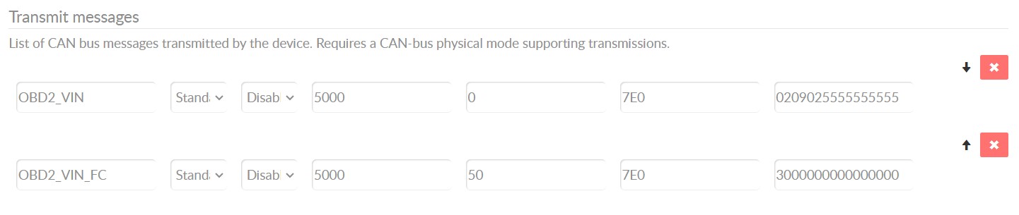
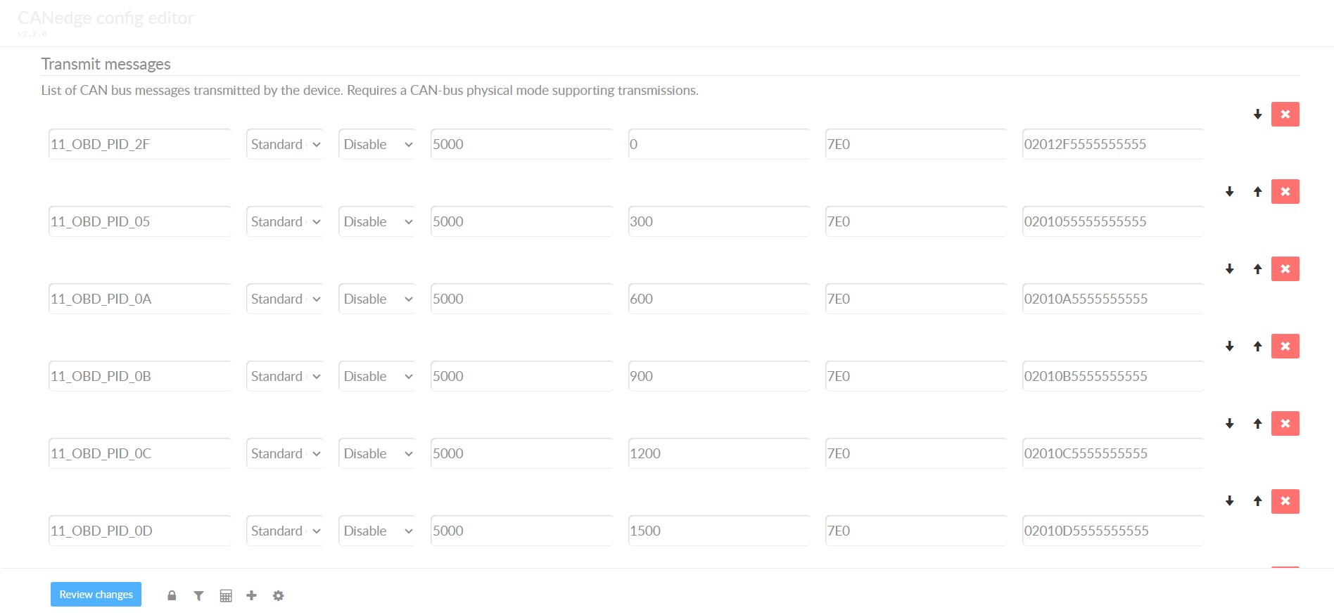 obd2-transmit-list-example-canedge
CANedge OBD2 Transmit List Example: An example configuration of an OBD2 transmit list in CANedge, showing a selection of OBD2 PIDs configured for periodic request transmission.
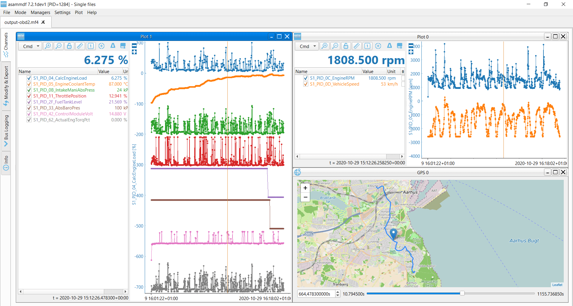 OBD2 data decoded visual plot asammdf CAN bus DBC file
Decoded OBD2 Data Plot in asammdf: A visual plot of decoded OBD2 data in asammdf software, demonstrating how raw OBD2 data can be converted into meaningful physical values using a DBC file for analysis and visualization.
Step #3: DBC Decode Raw OBD2 Data for Analysis
To effectively analyze and visualize your logged OBD2 data, you need to decode the raw data bytes into ‘physical values’ such as km/h or °C.
The necessary decoding information can be found in ISO 15031-5/SAE J1979 and online resources like Wikipedia. For convenience, we provide a free OBD2 DBC file that simplifies DBC decoding of raw OBD2 data within most CAN bus software tools.
Decoding OBD2 data is slightly more complex than decoding standard CAN signals. This is because different OBD2 PIDs are transmitted using the same CAN ID (e.g., 0x7E8). Therefore, the CAN ID alone isn’t sufficient to uniquely identify the signals within the payload.
To address this, you must consider the CAN ID, OBD2 mode, and OBD2 PID together to correctly identify the signal. This technique is known as ‘extended multiplexing‘ and can be effectively implemented using DBC files.
CANedge: Your OBD2 Data Logging Solution
The CANedge provides an easy-to-use solution for recording OBD2 data directly to an 8-32GB SD card. Simply connect it to your vehicle’s OBD2 port to start logging and then decode the data using free software and APIs and our OBD2 DBC file.
OBD2 logger intro CANedge product details
Advanced OBD2: Multi-Frame Communication Examples (ISO-TP)
All OBD2 communication, as per ISO 15765-2, utilizes the ISO-TP (Transport Protocol). While many examples discussed so far involve single-frame communication, this section explores multi-frame communication scenarios.
Multi-frame OBD2 communication requires flow control frames (explained in our UDS introduction). In practice, a static flow control frame can be transmitted approximately 50 ms after the initial request frame, as demonstrated in the CANedge configuration example.
Analyzing multi-frame OBD2 responses requires CAN software or API tools that support ISO-TP, such as the CANedge MF4 decoders.
 OBD2-multi-frame-request-message-vehicle-identification-number
OBD2 Multi-Frame Request Example: An example of an OBD2 multi-frame request message, specifically for retrieving the Vehicle Identification Number (VIN), illustrating the use of ISO-TP for larger data requests.
Example 1: Retrieving the Vehicle Identification Number (VIN) via OBD2
The Vehicle Identification Number (VIN) is crucial for telematics, diagnostics, and various other applications (see our UDS introduction for more details). To retrieve the VIN from a vehicle using OBD2 requests, you use Mode 0x09 and PID 0x02:
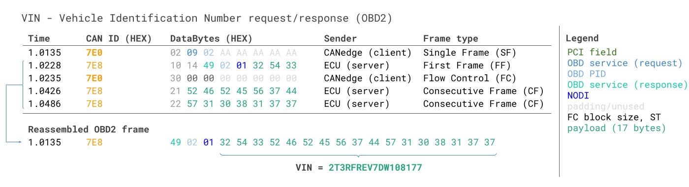 VIN Vehicle Identification Number OBD2 Example multi-frame
The diagnostic tool sends a Single Frame request with the PCI field (0x02), request service identifier (0x09), and PID (0x02).
The vehicle responds with a First Frame containing the PCI, total message length (0x014 = 20 bytes), mode (0x49, which is 0x09 + 0x40), and PID (0x02). Following the PID is the byte 0x01, representing the Number Of Data Items (NODI), which is 1 in this case (refer to ISO 15031-5 / SAE J1979 for details). The remaining 17 bytes contain the VIN, which can be converted from HEX to ASCII using methods described in our UDS introduction.
Example 2: OBD2 Multi-PID Request (Requesting 6 PIDs at Once)
External tools can request up to 6 Mode 0x01 OBD2 PIDs in a single request frame. The ECU should respond with data for all supported PIDs (omitting data for unsupported PIDs), using multi-frame responses via ISO-TP if necessary.
This feature allows for more efficient data collection at higher frequencies. However, it also means that the signal encoding is specific to the request method, making it difficult to use generic OBD2 DBC files for decoding. We generally do not recommend using this method for practical applications. Below is an example trace:
 Requesting multiple PIDs in one request
The multi-frame response is similar to the VIN example, but the payload includes both the requested PIDs and their corresponding data. In this example, the PIDs in the response are ordered similarly to the request order, which is common but not strictly mandated by ISO 15031-5.
Decoding these responses using generic DBC files is challenging. Therefore, we advise against this approach for practical data logging unless you are using tools specifically designed to handle multi-PID requests. Effectively, you would be dealing with extended multiplexing, complicated by the need to account for the specific payload position of each PID in your DBC file. This becomes even more complex when sending multiple such multi-PID requests, as it becomes difficult to uniquely identify messages.
Workarounds might involve custom scripts and recording the transmit messages from your diagnostic tool. The script could then interpret responses based on the corresponding requests. However, such approaches are generally difficult to scale and manage.
Example 3: Retrieving OBD2 Diagnostic Trouble Codes (DTCs)
You can use OBD2 to request emissions-related Diagnostic Trouble Codes (DTCs) using Mode 0x03, ‘Show stored Diagnostic Trouble Codes’. No PID is included in the request. The target ECU(s) will respond with the number of DTCs stored (possibly zero if no DTCs are present), with each DTC occupying 2 data bytes. Multi-frame responses are required when more than 2 DTCs are stored.
The 2-byte DTC value is typically structured as per ISO 15031-5/ISO 15031-6. The first 2 bits define the ‘category’, and the remaining 14 bits form a 4-digit hexadecimal code, as shown in the visual. Decoded DTC values can be looked up using OBD2 DTC lookup tools like repairpal.com.
The example below shows a request to an ECU that has 6 DTCs stored.
OBD2 DTC Decoding Example: An example of OBD2 DTC (Diagnostic Trouble Code) decoding, illustrating how a 2-byte DTC value is interpreted into category and a 4-digit code, and how these codes can be looked up for detailed fault descriptions.
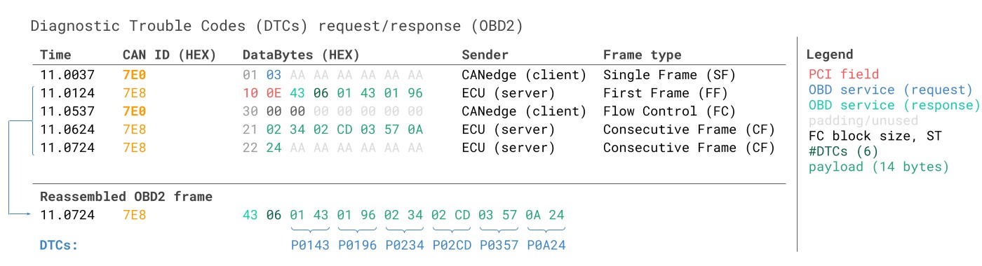 OBD2 Diagnostic Trouble Codes DTC CAN Bus Request Response Example
OBD2 Data Logging: Real-World Use Cases
OBD2 data from cars and light trucks has diverse applications across various industries:
Vehicle Data Logging from Cars
OBD2 data logging in cars can be used for applications like reducing fuel consumption, improving driving habits, testing prototype components, and insurance telematics.
OBD2 logger product link
Real-time Vehicle Diagnostics
OBD2 interfaces facilitate real-time streaming of human-readable OBD2 data, essential for diagnosing vehicle issues and performance monitoring.
OBD2 streaming interface link
Predictive Vehicle Maintenance
Cars and light trucks equipped with IoT OBD2 loggers can be monitored in the cloud to predict and prevent breakdowns, enabling proactive maintenance.
Predictive maintenance solutions link
Vehicle Black Box Recording
An OBD2 logger can serve as a ‘black box’ for vehicles or equipment, providing crucial data for accident analysis, dispute resolution, and detailed diagnostics.
CAN bus black box logger link
Do you have a specific OBD2 data logging application in mind? We offer free consultation to discuss your needs!
Contact us for expert advice
For more in-depth guides, explore our tutorials section or download our comprehensive ‘Ultimate Guide’ PDF.
Ready to start logging or streaming OBD2 data?
Get your OBD2 data logger today!
Buy OBD2 Data Loggers Now Contact us for assistance
Further Reading Recommendations:
OBD2 DATA LOGGER: EASILY LOG & CONVERT OBD2 DATA
 CANedge2 – Dual CAN Bus Telematics Dongle CANEDGE2 – PRO CAN IoT LOGGER
[