Delving into automotive diagnostics can seem daunting, but with a systematic approach and a bit of hands-on spirit, tackling issues like a faulty wheel speed sensor on your Toyota becomes manageable. Recently, while troubleshooting a suspected wheel speed sensor problem, I took apart the interior of my Toyota to access the sensor wires and gather some data. This process highlighted a couple of key points for anyone working on similar Toyota models, particularly when thinking about using OBD2 diagnostic tools down the line.
Initially, accessing the sensor wires involved quite a bit of interior disassembly. Removing the side panel felt like a significant undertaking, requiring the removal of numerous components. However, I realized a potentially simpler approach might exist. For future diagnostics, especially when using an OBD2 scanner to pinpoint a wheel speed sensor issue, it might be sufficient to just remove the seat and peel back the carpet. While this might offer less direct access compared to fully removing the side panel, for tasks like back-probing sensor wires or checking connections after retrieving an OBD2 code related to a wheel speed sensor, it could be enough. I plan to verify this theory when reassembling the interior, testing access with just the seat removed.
For this particular diagnostic session, however, the interior was already disassembled, providing a clear view of the sensor area. Here’s a look into the rear hatch, showing the left side of the interior. The left rear brake light is visible on the left side of the image, and the area of interest, the wheel speed sensor, is located on the right side, near the open left rear door.
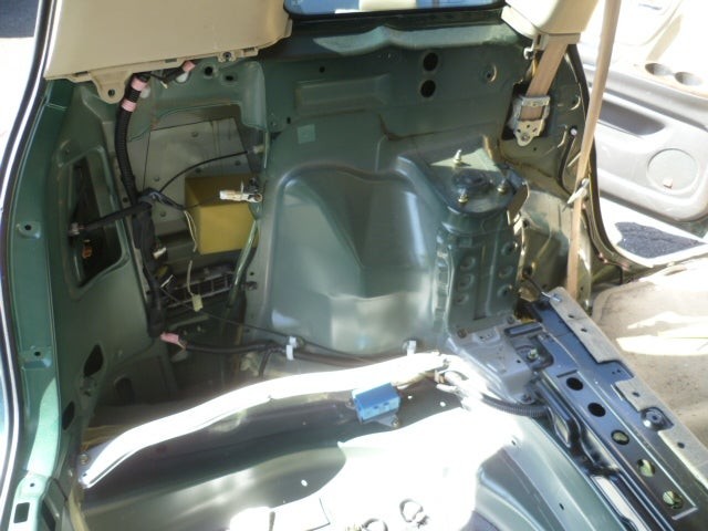 Rear hatch view of Toyota interior for wheel speed sensor access
This image gives a perspective from the rear hatch, looking towards the left side interior panel where the wheel speed sensor wiring is located. Understanding the physical location is crucial when using OBD2 codes to guide your visual inspection.
Another perspective, taken from inside the car where the rear seat would normally be, looking towards the rear, shows the sensor wiring as it enters from the wheel well and connects to its connector.
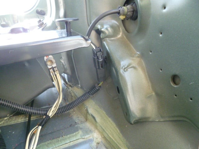 Close-up of Toyota wheel speed sensor wiring and connector
This closer view highlights the wheel speed sensor wiring and its connector. When your OBD2 scanner points to a specific wheel speed sensor, this visual helps in locating the exact connector for testing.
The next step involved disconnecting the sensor connector to measure the sensor’s resistance. Using a multimeter, the resistance was measured at approximately 1 Kilo Ohms. While the exact specification for a 2002 model wasn’t immediately available, a quick reference to the 2005 specification (0.9 to 1.3 Kilo Ohms) suggested the sensor was likely within the acceptable range. This resistance check is a basic but important step in confirming sensor health, even before deeper OBD2 diagnostics.
After confirming the resistance was within a reasonable range, the connector was reconnected. To further analyze the sensor’s signal output, an older piece of diagnostic equipment, a Micronta Transistorized Signal Tracer, was employed. This vintage tool, essentially an amplifier and speaker, is designed to trace audio signals.
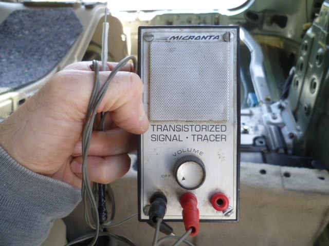 Micronta Transistorized Signal Tracer used for wheel speed sensor signal analysis
Using this signal tracer to listen to the wheel speed sensor output might seem unconventional compared to modern OBD2 scanners that display waveform data. However, the principle is similar: to verify if the sensor is generating a signal as the wheel rotates. The signal tracer effectively converted the sensor’s sine wave output into audible sound.
Driving the car with the signal tracer connected confirmed that the sensor was indeed producing a signal. As speed increased, both the pitch and volume of the sound from the speaker changed accordingly, indicating the sensor was reacting to wheel speed variations. Ideally, modern OBD2 scanners would display this signal as a waveform, allowing for a more detailed analysis of signal quality and consistency.
Unfortunately, despite confirming the sensor was outputting a signal, no obvious breaks or anomalies were detected in the signal that could explain the car’s ongoing issue. This meant that while the sensor appeared to be functioning, it wasn’t definitively ruled out as the source of the problem. This is a common scenario in automotive diagnostics: initial tests might not reveal a “smoking gun,” and further investigation is needed.
Moving forward, the next steps include examining the right rear sensor connector for comparison. Comparing readings between sensors can sometimes reveal subtle differences not immediately apparent with individual sensor testing. Additionally, clearing the OBD2 error code for the left rear sensor is important to see if the code reappears, which could provide further clues.
Finally, the question of a cracked tone ring is raised. A cracked tone ring, not completely broken but fractured, can cause intermittent or erratic wheel speed sensor readings. Understanding the symptoms of a cracked tone ring is crucial, as it might not always trigger a clear-cut sensor failure code but could still disrupt the ABS or traction control systems, which are closely monitored by the OBD2 system in your Toyota.
In conclusion, diagnosing wheel speed sensor issues in a Toyota, especially with the aid of OBD2 diagnostic tools, involves a combination of electrical testing, signal analysis, and careful observation. While sometimes unconventional methods like a signal tracer can be helpful, modern OBD2 scanners offer more comprehensive data and streamline the diagnostic process. This DIY exploration highlights the steps involved and underscores the importance of systematic troubleshooting when addressing automotive sensor problems in your Toyota.