Are you looking for a straightforward yet comprehensive guide to OBD2 and, more specifically, OBD2 data? This article provides an in-depth look at On-Board Diagnostics (OBD2), focusing on the crucial aspect of data parameters – often referred to as OBD2 PIDs (Parameter IDs). We’ll explore everything from the OBD2 connector and communication protocols to understanding and utilizing OBD2 data for vehicle diagnostics and performance monitoring.
This guide builds upon the foundational knowledge of OBD2, offering a more detailed exploration of OBD2 data parameters, making it the ultimate resource for anyone seeking to truly understand vehicle diagnostics.
You can also further enhance your knowledge by exploring our comprehensive CAN bus guide.
Decoding OBD2: More Than Just Error Codes
OBD2 is fundamentally your car’s self-diagnostic system. It’s a standardized protocol designed to provide access to vehicle diagnostic information, primarily emission-related data. However, the capabilities of OBD2 extend far beyond just identifying problems. Through OBD2 data parameters, you gain access to a wealth of real-time information about your vehicle’s operation.
You’re likely familiar with the check engine light, or malfunction indicator light (MIL), on your dashboard. This light is often triggered by issues detected by the OBD2 system. Mechanics use OBD2 scanners to connect to your car’s OBD2 16-pin connector, typically located near the steering wheel. These scanners send requests and receive responses containing Diagnostic Trouble Codes (DTCs) and, importantly, OBD2 data, such as speed, engine temperature, and fuel consumption. This OBD2 data is key to efficient and accurate troubleshooting.
Alt Text: OBD2 system in action, showing the malfunction indicator light and a mechanic using an OBD2 scanner to access vehicle diagnostics.
OBD2 Compatibility: Is Your Car Included?
The good news is that OBD2 is widely supported. Most modern non-electric cars are OBD2 compliant, and many utilize the CAN bus communication protocol. While a 16-pin OBD2 connector is a strong indicator, older vehicles with this connector might not fully support OBD2. Compliance is often linked to the vehicle’s region and year of manufacture:
 Does My Car Have OBD2?
Alt Text: Infographic illustrating OBD2 compliance by region and year, highlighting US and EU regulations for gasoline and diesel cars.
A Brief History of OBD2 and Data Standardization
OBD2’s origins are in California, driven by the California Air Resources Board (CARB) to monitor vehicle emissions starting in 1991. The Society of Automotive Engineers (SAE) played a crucial role in standardizing OBD2, defining DTCs and the universal OBD connector (SAE J1962).
The OBD2 standard’s implementation was a phased process:
- 1996: OBD2 becomes mandatory in the USA for cars and light trucks.
- 2001: OBD2 required in the EU for gasoline vehicles.
- 2003: EU extends OBD2 requirement to diesel vehicles (EOBD).
- 2005: OBD2 mandated in the US for medium-duty vehicles.
- 2008: US vehicles must adopt ISO 15765-4 (CAN) as the foundation for OBD2 communication.
- 2010: OBD2 becomes mandatory for heavy-duty vehicles in the US.
Alt Text: Graphic showcasing OBD2 history timeline, emphasizing emission control, exhaust standards, and the role of CAN bus in data communication.
Alt Text: Timeline visualization of OBD2 history, outlining key milestones in on-board diagnostics development and standardization across different years.
Alt Text: Conceptual image of OBD3 future trends, depicting remote diagnostics, emissions testing, cloud connectivity, and IoT integration for vehicle data.
The Future of OBD2: Data Access and Evolution
While OBD2 remains relevant, its future is evolving. Electric vehicles (EVs), initially exempt from OBD2 requirements, are presenting a shift. Most modern EVs don’t support standard OBD2 requests, often using OEM-specific UDS communication, making OBD2 data access challenging without reverse engineering.
Alternatives like WWH-OBD (World Wide Harmonized OBD) and OBDonUDS (OBD on UDS) are emerging to improve OBD communication by utilizing the UDS protocol. These aim to enhance OBD2 data richness and streamline data exchange.
The concept of OBD3 envisions adding telematics capabilities for remote emission checks. This involves integrating radio transponders for wireless transmission of VIN and DTCs for centralized monitoring. While convenient and cost-saving, this raises privacy concerns.
The automotive industry is also debating the future of OBD2 data access for third parties. Concerns exist about the unintended use of OBD2 for building data-driven economies, potentially leading to restricted access in the future. This could impact the availability of OBD2 data for aftermarket services.
Alt Text: Illustration depicting OBD2 connector removal from an electric vehicle, symbolizing potential data access limitations in EVs.
Deep Dive into OBD2 Standards and Data Parameters
OBD2 operates as a higher-layer protocol, similar to J1939, CANopen, and NMEA 2000, built upon lower-layer communication methods like CAN bus. OBD2 standards define the connector, communication protocols, and crucially, OBD2 Parameter IDs (PIDs), which are codes used to request specific OBD2 data.
These standards are structured within the 7-layer OSI model, with SAE and ISO standards covering various layers, reflecting US and EU standardization efforts. SAE J1979 and ISO 15031-5 are key for OBD2 data parameters, while SAE J1962 and ISO 15031-3 define the OBD connector.
Alt Text: OSI 7-layer model diagram comparing OBD2 and CAN Bus standards, highlighting ISO 15765 and ISO 11898 in relation to network layers.
Alt Text: OBD2 connector pinout diagram, showing socket female Type A DLC (Data Link Connector) with pin assignments and descriptions.
The OBD2 Connector: Your Gateway to Vehicle Data
The 16-pin OBD2 connector, standardized by SAE J1962 and ISO 15031-3, provides easy access to vehicle OBD2 data. This connector is typically located near the steering wheel, though its exact location can vary. Key features include:
- Pin 16: Battery power supply, often active even when the ignition is off.
- Pinout variations: Dependent on the communication protocol used.
- CAN bus prevalence: Pins 6 (CAN-H) and 14 (CAN-L) are commonly connected for CAN bus communication.
OBD2 Connector Types: A and B
You may encounter Type A and Type B OBD2 connectors. Type A is standard in cars, while Type B is more common in medium and heavy-duty vehicles. While pinouts are similar, Type A provides 12V power, and Type B provides 24V. Baud rates can also differ (cars often use 500K, heavy-duty vehicles 250K or 500K).
Type B connectors have a distinguishing interrupted groove, making Type B adapters compatible with both Type A and B sockets, but Type A adapters incompatible with Type B sockets.
Alt Text: Comparison diagram of OBD2 Connector Type A and Type B, illustrating differences in pin configuration, voltage (12V vs 24V), and application in cars, vans, and trucks.
Alt Text: Diagram contrasting OBD2 and CAN bus, emphasizing the role of ISO 15765 in standardizing CAN bus for OBD2 communication.
OBD2 and CAN Bus: The Data Communication Backbone
Since 2008, CAN bus (ISO 15765-4, also known as Diagnostics over CAN or DoCAN) has been the mandatory lower-layer protocol for OBD2 in US vehicles. ISO 15765-4 standardizes the CAN interface for diagnostic equipment, focusing on:
- Bit-rate: 250K or 500K.
- CAN IDs: 11-bit or 29-bit.
- Specific CAN IDs for OBD requests and responses.
- Data length: 8 bytes per diagnostic CAN frame.
- Cable length: Max 5 meters for the OBD2 adapter cable.
OBD2 CAN Identifiers: Addressing and Data Flow
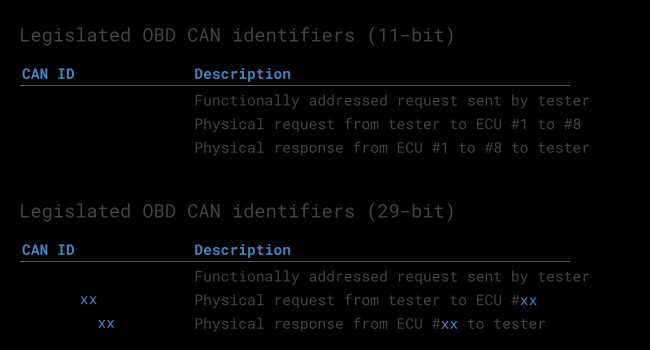
OBD2 communication relies on request/response message exchanges. 11-bit CAN IDs are common in cars, with ‘Functional Addressing’ ID 0x7DF used to query all OBD2-compatible ECUs. ‘Physical Addressing’ IDs (0x7E0-0x7E7) target specific ECUs. Response IDs typically range from 0x7E8-0x7EF, with 0x7E8 (ECM) and 0x7E9 (TCM) being frequent.
Some vehicles, especially vans and heavy-duty vehicles, use 29-bit CAN identifiers for OBD2. Here, ‘Functional Addressing’ ID is 0x18DB33F1, with responses in the range of 0x18DAF100 to 0x18DAF1FF. The response ID is also represented as J1939 PGN 0xDA00 (55808).
Alt Text: Illustration of OBD2 protocol request and response frames, detailing PID (Parameter ID) data parameters within the communication structure.
 OBD2 OBD CAN bus Identifiers 7DF 7E8 7E0
Alt Text: Diagram contrasting OBD2 and proprietary CAN bus systems, highlighting differences in data access and OEM-specific protocols.
OBD2 vs. Proprietary CAN Protocols: Understanding the Difference
Vehicle ECUs operate using OEM-specific proprietary CAN protocols, independent of OBD2. These protocols are brand, model, and year-specific, and typically not publicly accessible. OBD2 is an additional, parallel protocol for standardized diagnostics.
Connecting a CAN bus data logger to the OBD2 connector might capture OEM-specific CAN data, but in newer vehicles, gateways often restrict access, allowing only OBD2 communication through the OBD2 port. Think of OBD2 as a supplementary higher-layer protocol existing alongside the OEM’s primary communication network.
Bit-rate and ID Validation: Ensuring Correct Communication
OBD2 can use 250K or 500K bit-rates and 11-bit or 29-bit CAN IDs, resulting in four possible combinations. Modern cars commonly use 500K and 11-bit IDs. ISO 15765-4 provides initialization sequences to determine the correct combination, relying on the mandatory support for OBD2 mode 0x01 PID 0x00 and detecting CAN error frames caused by incorrect bit-rates.
Newer ISO 15765-4 versions account for OBDonUDS alongside OBDonEDS. This article primarily focuses on OBDonEDS (OBD2, SAE OBD, EOBD, ISO OBD) and not WWH-OBD/OBDonUDS used mainly in EU trucks/buses. Testing tools can probe for OBDonUDS support using UDS requests with service 0x22 and DID 0xF810.
Alt Text: Flowchart illustrating OBD2 bit-rate and CAN ID validation process according to ISO 15765-4, outlining steps for protocol detection and verification.
Alt Text: Graphic depicting OBD2 standards including CAN (ISO 15765), KWP2000, SAE J1850, and ISO 9141, showcasing the five lower-layer protocols for OBD2.
Five Lower-Layer OBD2 Protocols: A Historical Perspective
While CAN (ISO 15765) is now dominant, older vehicles (pre-2008) might use other lower-layer OBD2 protocols. Understanding these is useful for diagnosing older cars. These include:
- ISO 15765 (CAN bus): Mandatory in US cars from 2008 onwards, now widely used.
- ISO14230-4 (KWP2000): Common in 2003+ Asian cars.
- ISO 9141-2: Used in EU, Chrysler, and Asian cars (2000-2004).
- SAE J1850 (VPW): Primarily in older GM vehicles.
- SAE J1850 (PWM): Primarily in older Ford vehicles.
ISO-TP: Transporting OBD2 Messages Beyond 8 Bytes
OBD2 communication on CAN bus utilizes ISO-TP (ISO 15765-2) for messages exceeding 8 bytes. This transport protocol enables segmentation, flow control, and reassembly, essential for transmitting larger OBD2 data payloads like VIN or DTCs.
For smaller OBD2 data transmissions within a single CAN frame, ISO 15765-2 uses ‘Single Frame’ (SF) format. The first byte indicates payload length, leaving 7 bytes for OBD2 data.
Alt Text: Diagram illustrating ISO 15765-2 ISO-TP OBD2 frame types, including Single Frame, First Frame, Consecutive Frame, and Flow Control, for data segmentation and transmission.
Decoding the OBD2 Diagnostic Message: Modes and PIDs
A raw ‘Single Frame’ OBD2 CAN message comprises an identifier, data length (PCI field), and data. The data section includes Mode, Parameter ID (PID), and data bytes. Understanding these components is crucial for interpreting OBD2 data.
Alt Text: Breakdown of OBD2 message structure, explaining OBD-ii message components including PIDs (Parameter IDs), Mode, Identifier, and Data Bytes.
Example: Requesting and Interpreting Vehicle Speed Data
Consider requesting ‘Vehicle Speed’ data. An external tool sends a request message with CAN ID 0x7DF, containing Mode 0x01 and PID 0x0D. The vehicle responds with CAN ID 0x7E8, including the speed value in the 4th byte. For instance, a response byte of 0x32 translates to 50 km/h after applying OBD2 PID decoding rules.
Alt Text: OBD2 request and response example using CAN IDs 7DF and 7E8, specifically for vehicle speed parameter, demonstrating data exchange.
Alt Text: OBD2 PID example focusing on Vehicle Speed with PID 0D, detailing request and response data structure for retrieving speed information.
Alt Text: OBD2 services modes diagram illustrating the 10 diagnostic services or modes, including current data, freeze frame, and clear DTC (Diagnostic Trouble Codes) functionalities.
The 10 OBD2 Services (Modes): Accessing Different Data Types
OBD2 defines 10 diagnostic services or modes. Mode 0x01 provides real-time OBD2 data, while others handle DTCs and freeze frame data. Vehicles may not support all 10 modes and can include OEM-specific modes.
In OBD2 messages, the mode is in the second byte of the request (e.g., 0x01). In the response, 0x40 is added to the requested mode (e.g., 0x41 for mode 0x01).
OBD2 Parameter IDs (PIDs): The Key to Specific Data Points
Each OBD2 mode contains Parameter IDs (PIDs). Mode 0x01, for example, includes approximately 200 standardized PIDs for real-time OBD2 data like speed, RPM, and fuel level. However, vehicles typically support only a subset of these PIDs.
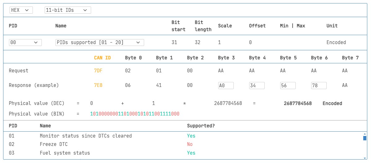
PID 0x00 in mode 0x01 is mandatory for emission-related ECUs supporting OBD2. It indicates support for PIDs 0x01-0x20, serving as an OBD2 data compatibility test. PIDs 0x20, 0x40, and so on, reveal support for subsequent mode 0x01 PID ranges.
Alt Text: Re-used image – Illustration of OBD2 protocol request and response frames, detailing PID (Parameter ID) data parameters within the communication structure.
 OBD2 PID overview tool
Alt Text: Screenshot of an OBD2 PID overview tool, showcasing service 01 functionality for displaying and managing OBD2 Parameter IDs.
OBD2 PID Overview Tools: Simplifying Data Interpretation
SAE J1979 and ISO 15031-5 appendices provide scaling information for standard OBD2 PIDs, enabling conversion of raw data into physical values. Tools like our OBD2 PID overview tool aid in constructing request frames and dynamically decoding responses, simplifying OBD2 data analysis.
OBD2 PID overview tool
Practical Guide: Logging and Decoding OBD2 Data
Let’s walk through logging OBD2 data using a CANedge data logger. The CANedge allows custom CAN frame transmission, making it suitable for OBD2 logging. Connect it to your vehicle using an OBD2-DB9 adapter cable.
Alt Text: Diagram illustrating OBD2 PID data logging request using CAN IDs 7df and 7e8, depicting data flow for parameter identification and logging.
 OBD2 bit rate test
Alt Text: Image showing OBD2 bit rate test validation, indicating successful CAN frame transmission at 500K bit rate for OBD2 communication.
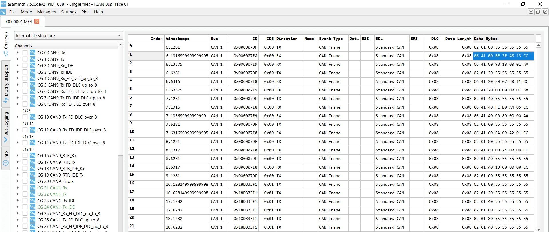
 OBD2 Supported PIDs Test
Alt Text: Screenshot from asammdf software displaying OBD2 Supported PIDs Test responses, showing validation of Parameter IDs and vehicle responses.
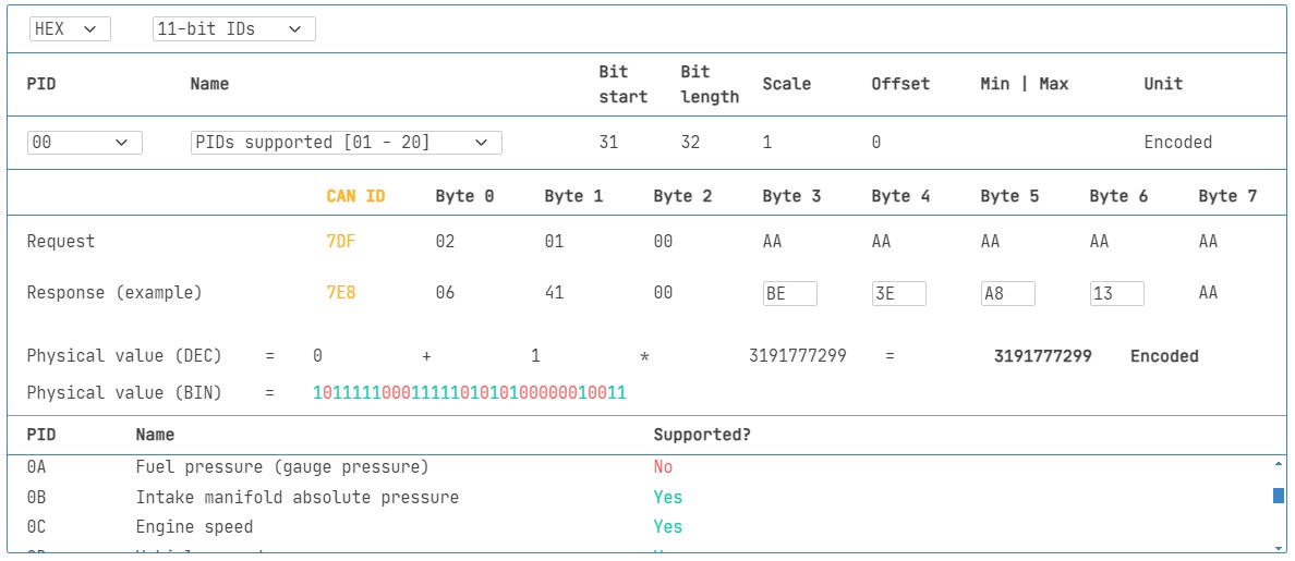
 Review supported PIDs via OBD2 lookup tool
Step #1: Validate Bit-rate, IDs, and Supported PIDs
Follow ISO 15765-4 guidelines to determine the correct bit-rate and IDs. Use CANedge for testing:
- Test 500K bit-rate, then 250K if unsuccessful.
- Use the validated bit-rate for further communication.
- Send ‘Supported PIDs’ requests and analyze responses.
- Determine 11-bit or 29-bit IDs from response IDs.
- Identify supported PIDs from response data.
Plug-and-play configurations are available for these tests. Most post-2008 non-EV cars support 40-80 PIDs using 500K, 11-bit CAN IDs, and OB