Disclaimer: This guide is for informational purposes only. I am not a professional, just an enthusiast sharing my DIY experience. Follow these steps at your own risk. I am not responsible for any damage or issues that may arise from attempting this project, including but not limited to harness malfunction, ECU damage, or unintended consequences. Proceed with caution and ensure you understand each step before attempting it.
Creating a custom OBD2 (On-Board Diagnostics II) connector harness can be a useful skill for automotive enthusiasts and DIY mechanics. This guide will walk you through the process of building a simple harness using a 16 Pin Connector Obd2, focusing on connecting essential pins for basic diagnostic functions. This project is designed for those who need a customized connection interface, and it utilizes a 4-pin connector for a streamlined setup.
Tools and Parts You Will Need
Before starting, gather the necessary tools and parts:
- Wire strippers/cutters
- Needle-nose pliers
- Soldering iron (recommended for a robust connection)
- Molex crimping tool (optional, but helpful for professional crimping)
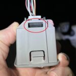
- 4-pin connector (link to part used; pin/wire size = 22-16AWG; insulation/seal size = 1.3-1.7mm)
- OBD-II Cable (link to part used)
For cost-saving, if you have spare wires, you can purchase just the female OBD-II connector and use your own wires to connect the OBD-II and 4-pin connectors. Ensure your wire size is compatible with the 4-pin connector specifications.
From the 16 pins available on the OBD2 connector, we will only be utilizing four crucial connections for this harness:
- Pin 4: Chassis Ground (orange wire on the OBD2 cable)
- Pin 6: CAN (J-2234) High (green wire on the OBD2 cable)
- Pin 14: CAN (J-2234) Low (brown w/white stripe wire on the OBD2 cable)
- Pin 16: Battery Power (green w/white stripe wire on the OBD2 cable)
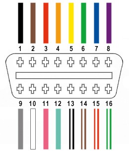 OBD2 16 pin connector pinout diagram showing pins 4, 6, 14, and 16 for custom harness wiring
Step-by-Step Guide to Building Your Custom OBD2 Harness
Follow these steps to assemble your custom OBD2 connector harness:
Step 1: Preparing the Wires
Start by preparing the OBD-II cable. It’s often recommended to twist pairs of wires for signal integrity, especially for CAN bus communication. Begin by carefully removing the outer sheath and shielding from the OBD2 cable to access the internal wires. Identify and separate the four wires you will be using (pins 4, 6, 14, and 16 as listed above). Bundle the remaining 12 wires and secure them out of the way using a zip tie to keep your workspace tidy.
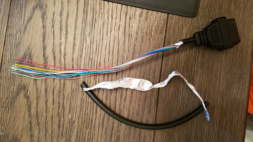 Preparing OBD2 cable wires by stripping sheath and shielding for custom connector build
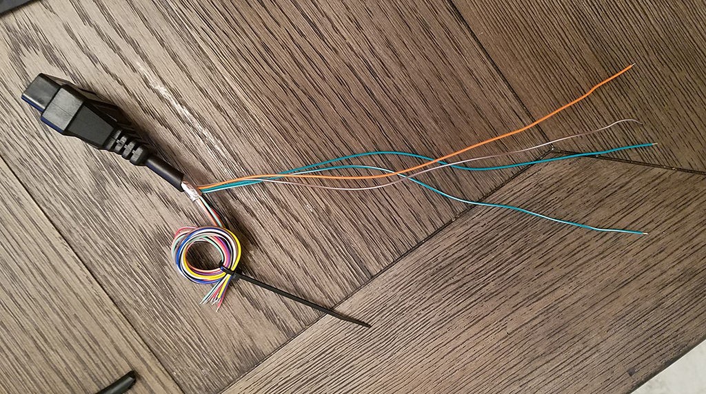 Four essential wires isolated from OBD2 cable for 16 pin connector harness project
The wires in the OBD2 cable are typically 26AWG, which is slightly smaller than the 22AWG minimum recommended for the pins of the 4-pin connector we are using. To ensure a secure connection, we need to “thicken” the wire ends. Carefully strip about 3/8″ of insulation from the end of each of the four selected wires. Fold the exposed wire strands over onto themselves and twist them tightly. This will effectively double the wire thickness, making it more suitable for the connector pins.
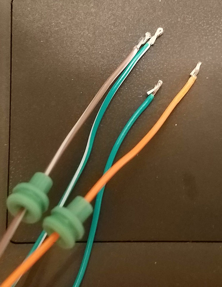 Rubber seals ready for installation on wires for 4-pin connector assembly
Before attaching the pins, slide a rubber seal onto each of the prepared wires. These seals are crucial for protecting the connection from moisture and debris once assembled into the 4-pin connector housing.
Step 2: Attaching Pins to the Wires
Now, take the pins for the 4-pin connector. Each pin has two sets of prongs. The front prongs are designed to crimp onto the exposed wire, and the rear prongs are for crimping onto the wire seal. Insert the exposed wire into the front of the pin, ensuring it aligns with the front prongs. Due to the small gauge of the wire, using needle-nose pliers to hold the wire in place during this step can be very helpful.
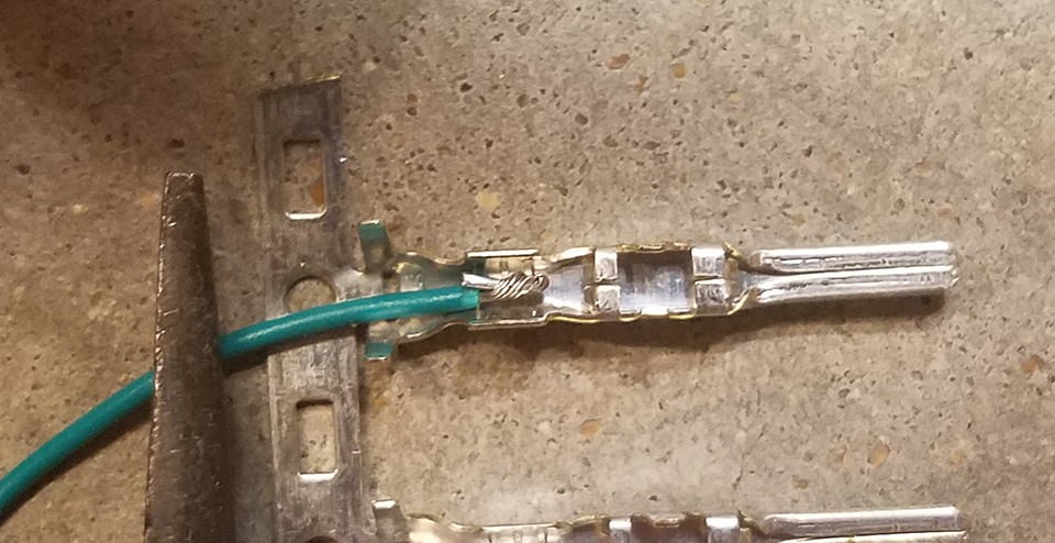 Close-up showing small gauge wire and 4-pin connector pin before soldering
For a reliable and robust connection, soldering the wire to the pin connector is highly recommended. Soldering provides a solid mechanical and electrical bond, especially beneficial when working with smaller gauge wires. If you are comfortable with soldering, apply a small amount of solder to the area where the wire meets the pin. Ensure the solder flows smoothly and creates a secure joint.
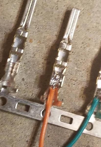 Soldering wire to pin connector for robust electrical connection in OBD2 harness
If you prefer crimping, and have a Molex crimping tool, use it to crimp the front prongs securely around the wire. If you don’t have a specialized crimping tool, needle-nose pliers can be used as an alternative. Carefully fold one prong at a time over the wire, using the pliers at an angle to get a tight crimp. For added security, you can gently squeeze the prongs further down with the pliers to ensure a firm grip.
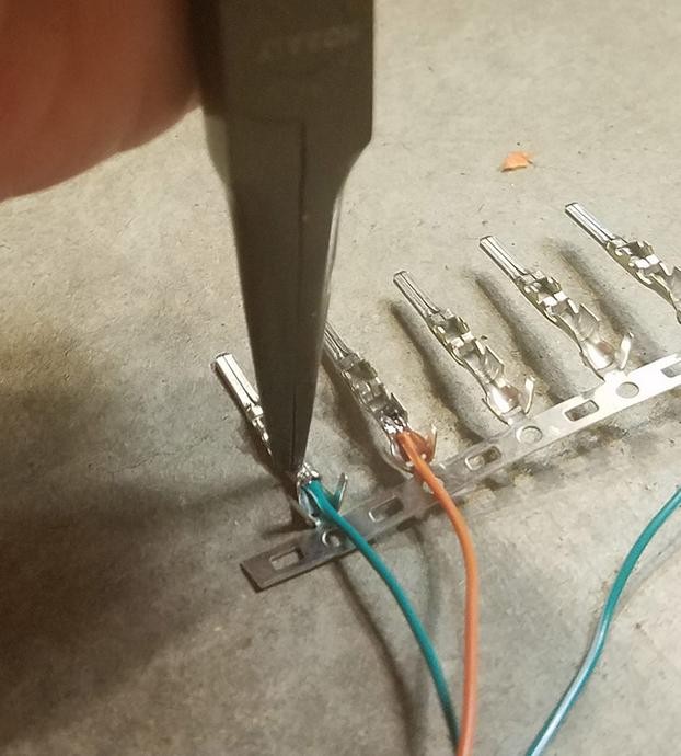 Crimping pin connector prongs over wire using needle-nose pliers as alternative to specialized tool
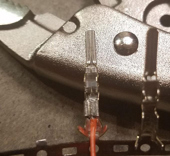 Secured wire within pin connector after crimping process for OBD2 harness construction
Next, slide the rubber seal up against the rear prongs of the pin. Use the same crimping technique as before to fold these prongs over the rubber seal. This will secure the seal in place, providing strain relief and environmental protection for the connection.
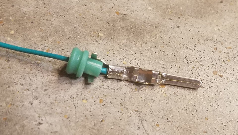 Positioning rubber seal for crimping onto 4-pin connector pin to ensure environmental protection
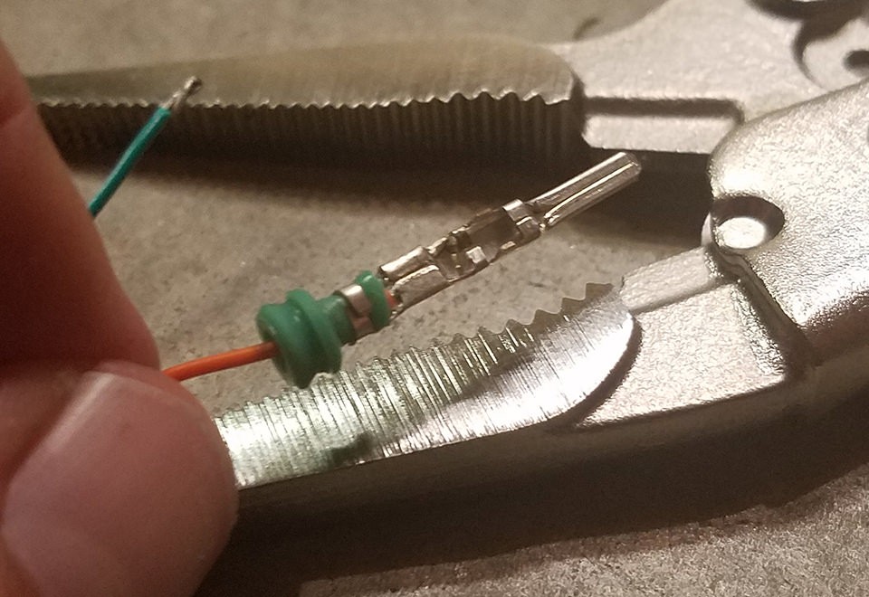 Crimping prongs over rubber seal on 4-pin connector pin for secure and sealed wire connection
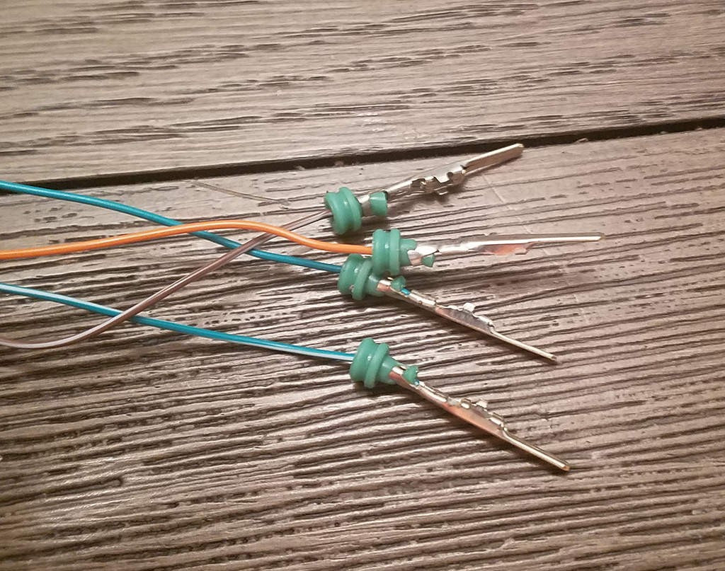 Completed wire and pin assembly ready for insertion into 4-pin connector housing for OBD2 harness
Step 3: Assembling the Connector
It’s often advised to twist specific pairs of wires together, particularly for CAN bus systems, to minimize interference and improve signal quality. Pair and twist the wires as follows:
- Pin 4 (orange) / Pin 16 (green w/white stripe) – Power Pair
- Pin 6 (green) / Pin 14 (brown w/white stripe) – CAN Bus Pair
Finally, insert the completed pins into the 4-pin connector housing in the correct orientation. Refer to the pinout diagram below for proper placement:
- Slot A: Pin 14 (brown w/white stripe) – CAN Low
- Slot B: Pin 6 (green) – CAN High
- Slot C: Pin 16 (green w/white stripe) – Battery Power
- Slot D: Pin 4 (orange) – Chassis Ground
Insert each pin into the rear of the connector housing until you hear a click, indicating it is locked securely in place. Using needle-nose pliers can help to gently pull the wire from the front to ensure the pin is fully seated and locked.
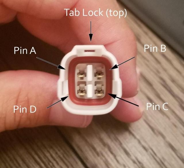 Pinout diagram for 4-pin connector showing correct wire insertion order for custom OBD2 harness
Testing Your Harness
With your custom OBD2 harness assembled, it’s time to test it. Connect your harness to your vehicle’s OBD2 port and a compatible diagnostic tool. Power up the tool and attempt to read vehicle data or check for diagnostic trouble codes (DTCs). Successfully reading data or clearing codes confirms that your harness is functioning correctly.
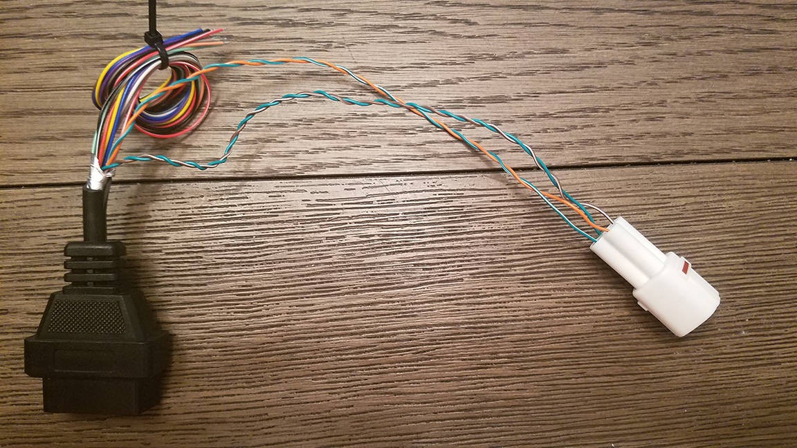 Finished custom 16 pin OBD2 connector harness ready for vehicle diagnostic use
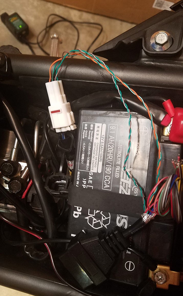 Close-up view of completed custom OBD2 harness and 4-pin connector assembly
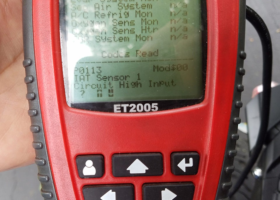 Successful OBD2 diagnostic scan using DIY 16 pin connector harness to check and clear error codes
Conclusion
Congratulations! You have successfully built a custom 16 pin OBD2 connector harness. This DIY project can provide a cost-effective solution for specific diagnostic needs or custom automotive electronics projects. Always double-check your connections and wiring before use to ensure safety and proper functionality. If you encounter any issues or have questions, consult with automotive electrical experts or refer to your vehicle’s service manual.
