Diagnosing issues with your 2007 Ford F-150 often starts with checking the OBD2 port for diagnostic trouble codes. However, if your OBD2 scanner isn’t powering up when connected to your truck, a blown fuse might be the culprit. Understanding the fuse box layout and knowing which fuse to check is crucial for a quick diagnosis. This guide will walk you through the fuse box locations and diagrams for the 2007 Ford F-150, specifically highlighting the fuse related to your OBD2 port, ensuring you can get your diagnostic process back on track.
Your 2007 Ford F-150 is equipped with multiple fuse boxes, each serving different electrical circuits. For our focus on the OBD2 port, we’ll primarily be looking at the passenger compartment fuse panel, which is also known as the power distribution box. Let’s explore this and the other fuse box locations to give you a complete picture.
Fuse Box Locations on the 2007 Ford F-150
The 2007 F-150 utilizes up to three different fuse box locations:
-
Passenger Compartment Fuse Panel: This is the primary fuse box and the one most relevant to your OBD2 port. It’s typically located inside the cabin, often on the passenger side, behind a panel in the dashboard or under the glove compartment.
-
Auxiliary Relay Box: There are two types of auxiliary relay boxes depending on whether your F-150 is equipped with Daytime Running Lamps (DRL). These boxes are usually found in the engine compartment and house relays and fuses for various vehicle systems.
Let’s delve deeper into each fuse box, starting with the most important one for your OBD2 diagnostics.
Passenger Compartment Fuse Panel Diagram
The passenger compartment fuse panel is where you’ll find the fuse that powers your OBD2 diagnostic connector. Locating and identifying the correct fuse here is key.
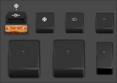
 2007 Ford F-150 passenger compartment fuse panel diagram
According to the diagram and fuse list, the fuse related to the diagnostic connector is Fuse #41, a 20A Mini fuse labeled “Cigar lighter, Diagnostic connector power”. If your OBD2 scanner is not receiving power, this is the first fuse you should inspect.
Here’s a table detailing the fuses in the passenger compartment fuse panel for your 2007 Ford F-150:
| Type | No. | Description |
|---|---|---|
| Fuse MINI 10A | 1 | Run/Accessory – Wipers, Instrument cluster, Audio for XL/STX |
| Fuse MINI 20A | 2 | Stop/Turn lamps, Brake on/off switch, Hazard flashers |
| Fuse MINI 7.5A | 3 | Power mirrors, Memory seats and pedals, Driver power seat |
| Fuse MINI 10A | 4 | DVD battery power, Power fold mirror |
| Fuse MINI 7.5A | 5 | Keep alive memory for Powertrain Control Module (PCM) and climate control module |
| Fuse MINI 15A | 6 | Parklamps, BSM, Instrument panel illumination |
| Fuse MINI 5A | 7 | Radio (start signal) |
| Fuse MINI 10A | 8 | Heated mirrors, Switch indicator |
| Fuse MINI 20A | 9 | Fuel pump relay, Fuel injectors, Intake manifold runner control [4.2L] |
| Fuse MINI 20A | 10 | Trailer tow back-up lamps relay (PCB1), Trailer tow parklamp relay (R201) |
| Fuse MINI 10A | 11 | A/C clutch, 4×4 solenoid |
| Fuse MINI 5A | 12 | PCM relay coil |
| Fuse MINI 10A | 13 | Climate control module power, Flasher relay |
| Fuse MINI 10A | 14 | Back-up lamp and Daytime Running Lamps (DRL) relay coil, A/C pressure switch, Redundant speed control switch, Heated PCV [5.4L], Trailer tow back-up lamps relay coil, ABS, Reverse park aid, EC mirror, Navigation radio (reverse input) |
| Fuse MINI 5A | 15 | Overdrive cancel, Cluster, Traction control switch |
| Fuse MINI 10A | 16 | Brake-shift interlock solenoid |
| Fuse MINI 15A | 17 | Fog lamp relay (R202) |
| Fuse MINI 10A | 18 | Run/Start feed – Overhead power point, Electrochromatic mirror, Heated seats, BSM, Compass, RSS (Reverse Sensing System) |
| Fuse MINI 10A | 19 | Restraints (Air bag module), OCS |
| Fuse MINI 10A | 20 | Battery feed for overhead power point |
| Fuse MINI 15A | 21 | Cluster keep alive power |
| Fuse MINI 10A | 22 | Delayed accessory power for audio, power door lock switch and moon roof switch illumination |
| Fuse MINI 10A | 23 | RH low beam headlamp |
| Fuse MINI 15A | 24 | Battery saver power for demand lamps |
| Fuse MINI 10A | 25 | LH low beam headlamp |
| Fuse MINI 20A | 26 | Horn relay (PCB3), Horn power |
| Fuse MINI 5A | 27 | Passenger Air bag Deactivation (PAD) warning lamp, Cluster RUN /START power |
| Fuse MINI 5A | 28 | SecuriLock transceiver (PATS), PCM IGN monitor |
| Fuse MINI 15A | 29 | PCM 4×4 power |
| Fuse MINI 15A | 30 | PCM 4×4 power |
| Fuse MINI 20A | 31 | Radio power, Satellite radio module |
| Fuse MINI 15A | 32 | Vapor Management Valve (VMV), A/C clutch relay, Canister vent, Heated Exhaust Gas Oxygen (HEGO) sensors #11 and #21, CMCV, Mass Air Flow (MAF) sensor, VCT, Heated Positive Crankcase Ventilation (PCV) valve [4.2L engine], CID sensor [4.2L engine, 4.6L/4.2L EGR] , Electronic fan clutch [4.6L/5.4L engines] |
| Fuse MINI 15A | 33 | Shift solenoid, CMS #12 and #22, Ignition coils |
| Fuse MINI 15A | 34 | PCM power |
| Fuse MINI 20A | 35 | Instrument cluster high beam indicator, High beam headlamps |
| Fuse MINI 10A | 36 | Trailer tow right turn/stop lamps |
| Fuse MINI 20A | 37 | Rear power point, Center console power point |
| Fuse MINI 25A | 38 | Subwoofer power |
| Fuse MINI 20A | 39 | Instrument panel power point |
| Fuse MINI 20A | 40 | Low beam headlamps, DRL |
| Fuse MINI 20A | 41 | Cigar lighter, Diagnostic connector power |
| Fuse MINI 10A | 42 | Trailer tow left turn/stop lamps |
| Fuse FMX/JCase 30A | 101 | Starter solenoid |
| Fuse FMX/JCase 20A | 102 | Ignition switch feed |
| Fuse FMX/JCase 20A | 103 | ABS valves |
| Fuse FMX/JCase 30A | 105 | Electric trailer brakes |
| Fuse FMX/JCase 30A | 106 | Trailer tow battery charge |
| Fuse FMX/JCase 30A | 107 | Power door locks (BSM) |
| Fuse FMX/JCase 30A | 108 | Passenger power seat |
| Fuse FMX/JCase 30A | 109 | Driver power seat, Adjustable pedals, Memory module (pedals, seat, mirror) |
| Fuse FMX/JCase 30A | 111 | 4×4 relays |
| Fuse FMX/JCase 40A | 112 | ABS pump power |
| Fuse FMX/JCase 30A | 113 | Wipers and washer pump |
| Fuse FMX/JCase 40A | 114 | Heated backlite, Heated mirror power |
| Fuse FMX/JCase 20A | 115 | Not used (Spare) |
| Fuse FMX/JCase 30A | 116 | Blower motor |
| Fuse FMX/JCase 30A | 118 | Heated seats |
| Circuit breaker MAXI | 401 | Delayed accessory power: Power windows, Moon roof, Power sliding backlite (circuit breaker) |
| Relay | R01 | Starter solenoid |
| Relay | R02 | Accessory delay |
| Relay | R03 | Hi-beam headlamps |
| Relay | R04 | Heated backlite |
| Relay | R05 | Trailer tow battery charge |
| Relay | R06 | Blower motor |
| Relay | R201 | Trailer tow park lamps |
| Relay | R202 | Fog lamps |
| Relay | R203 | PCM |
Passenger Compartment Fuse Panel Diagram and Fuse List for 2007 Ford F-150, highlighting the Diagnostic Connector Power fuse.
Auxiliary Relay Box (with DRL) Diagram
If your 2007 F-150 is equipped with Daytime Running Lamps (DRL), it will have this auxiliary relay box. While less likely to be directly related to the OBD2 port power issue, it’s good to be aware of its location and function.
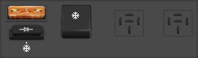
 2007 Ford F-150 auxiliary relay box diagram with DRL
Here is the fuse and relay listing for the Auxiliary Relay Box (with DRL):
| Type | No. | Description |
|---|---|---|
| Fuse ATO 5A | F03 | Clockspring illumination |
| Relay | R01 | 4×4 CCW |
| Relay | R02 | 4×4 CW |
| Relay | R03 | Daytime Running Lamps (DRL) high beam disable |
| Relay | R201 | (DRL) Daytime running lights |
| Relay | R202 | (A/C clutch) A/C magnetic clutch |
| Diode ATO | D01 | (A/C clutch) A/C magnetic clutch |
Auxiliary Relay Box Diagram (with DRL) for 2007 Ford F-150.
Auxiliary Relay Box (without DRL) Diagram
For 2007 F-150 models without Daytime Running Lamps, a slightly different auxiliary relay box is used.
 2007 Ford F-150 auxiliary relay box diagram without DRL
Below is the component list for the Auxiliary Relay Box (without DRL):
| Type | No. | Description |
|---|---|---|
| Fuse ATO 5A | F03 | Clockspring illumination |
| Diode ATO | D01 | A/C clutch |
| Relay | R202 | A/C clutch |
Auxiliary Relay Box Diagram (without DRL) for 2007 Ford F-150.
Troubleshooting Your 2007 F-150 OBD2 Port Fuse
When your OBD2 port isn’t working on your 2007 Ford F-150, follow these steps to check the fuse:
- Locate the Passenger Compartment Fuse Box: Refer to your owner’s manual for the precise location, but it’s commonly found on the passenger side interior.
- Identify Fuse #41: Using the diagram provided, locate fuse number 41, which is a 20A Mini fuse.
- Inspect the Fuse: Visually check the fuse. If the wire inside is broken or melted, the fuse is blown and needs replacement. You can also use a fuse tester for a more definitive check.
- Replace if Necessary: Replace the blown 20A fuse with a new fuse of the same type and amperage. Important: Always use the correct amperage fuse. Using a higher amperage fuse can damage your vehicle’s electrical system.
- Test Your OBD2 Port: After replacing the fuse, try connecting your OBD2 scanner again to see if it now powers up and communicates with your vehicle’s computer.
By following these steps and utilizing the fuse box diagrams, you can effectively diagnose and resolve a common issue preventing your OBD2 scanner from working on your 2007 Ford F-150. Remember to consult your vehicle’s repair manual for detailed instructions and safety precautions when working with your vehicle’s electrical system.