Understanding your 2010 Ford Escape’s fuse box is crucial for diagnosing and resolving electrical issues. Fuses protect your vehicle’s electrical circuits from overloads, and knowing their location and function can save you time and money on repairs. This guide provides a detailed look at the fuse box diagrams for your 2010 Ford Escape, along with information about the OBD2 port, which is essential for modern vehicle diagnostics. While this article primarily focuses on fuses, understanding the OBD2 port and its related systems is also vital for comprehensive vehicle maintenance.
Your Ford Escape has two main fuse boxes. Locating and understanding these is the first step in troubleshooting electrical problems, and can sometimes be related to issues diagnosed via the OBD2 port.
Passenger Compartment Fuse Panel Diagram
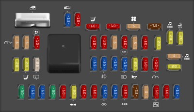
The passenger compartment fuse panel is located inside the vehicle. Consult the diagram below to identify the fuses in this location.
 2010 Ford Escape Passenger compartment fuse panel diagram
| Type | No. | Description |
|---|---|---|
| Fuse MINI 30A | 1 | Not used (spare) |
| Fuse MINI 15A | 2 | Brake On/Off switch |
| Fuse MINI 15A | 3 | Sync module |
| Fuse MINI 30A | 4 | Moon roof |
| Fuse MINI 10A | 5 | Keypad illumination, Brake Shift Interlock (BSI), Passenger compartment fuse panel |
| Fuse MINI 20A | 6 | Turn signals, Stop lamps |
| Fuse MINI 10A | 7 | Low beam headlamps (left) |
| Fuse MINI 10A | 8 | Low beam headlamps (right) |
| Fuse MINI 15A | 9 | Interior lights |
| Fuse MINI 15A | 10 | Backlighting |
| Fuse MINI 10A | 11 | Four wheel drive |
| Fuse MINI 7.5A | 12 | Power mirror switch |
| Fuse MINI 5A | 13 | Not used (spare) |
| Fuse MINI 10A | 14 | FCIM (radio buttons), Front display module, GPS module |
| Fuse MINI 10A | 15 | Climate control |
| Fuse MINI 15A | 16 | Not used (spare) |
| Fuse MINI 20A | 17 | All lock motor feeds, Liftgate release, Liftglass release |
| Fuse MINI 20A | 18 | Heated seat |
| Fuse MINI 25A | 19 | Rear wiper |
| Fuse MINI 15A | 20 | Datalink |
| Fuse MINI 15A | 21 | Fog lamps |
| Fuse MINI 15A | 22 | Park lamps |
| Fuse MINI 15A | 23 | High beam headlamps |
| Fuse MINI 20A | 24 | Horn relay |
| Fuse MINI 10A | 25 | Demand lamps |
| Fuse MINI 10A | 26 | Instrument panel cluster |
| Fuse MINI 20A | 27 | Ignition switch |
| Fuse MINI 5A | 28 | Radio |
| Fuse MINI 5A | 29 | Instrument panel cluster |
| Fuse MINI 5A | 30 | Not used (spare) |
| Fuse MINI 10A | 31 | Restraints control module |
| Fuse MINI 10A | 32 | Rear video camera module |
| Fuse MINI 10A | 33 | Not used (spare) |
| Fuse MINI 5A | 34 | Not used (spare) |
| Fuse MINI 10A | 35 | Four wheel drive, Electric power assist steering (EPAS), Park aid module, Active park assist module |
| Fuse MINI 5A | 36 | Passive anti-theft system (PATS) transceiver |
| Fuse MINI 10A | 37 | Climate control |
| Fuse MINI 20A | 38 | Subwoofer/Amp (premium radio) |
| Fuse MINI 20A | 39 | Radio, Radio Amplifier (navigation only) |
| Fuse MINI 20A | 40 | Front power point |
| Fuse MINI 15A | 41 | Driver/passenger door lock switches, Automatic dimming mirror, Compass, Ambient lighting, Moon roof, Camera display in mirror |
| Fuse MINI 10A | 42 | Not used (spare) |
| Fuse MINI 10A | 43 | Rear wiper logic, Heated seats relay, Instrument cluster |
| Fuse MINI 10A | 44 | Not used (spare) |
| Fuse MINI 5A | 45 | Front wiper logic, Blower motor relay |
| Fuse MINI 7.5A | 46 | Occupant classification system (OCS), Passenger airbag deactivation indicator (PADI) |
| Circuit breaker MAXI | 47 | Power windows |
| Relay | 48 | Delayed accessory relay |
This table details each fuse in the passenger compartment fuse panel, noting the fuse type, number, amperage, and the system it protects. For example, Fuse #20 (15A) is dedicated to the datalink connector, which is closely related to your vehicle’s OBD2 system. A problem with the OBD2 port might sometimes be fuse related, making this information valuable for diagnostics. Always refer to your owner’s manual for the most accurate and up-to-date information, as fuse allocations can sometimes vary based on vehicle options and production changes.
Power Distribution Box Diagram
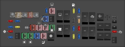
The power distribution box is typically located in the engine compartment. This fuse box contains fuses and relays for higher-current circuits.
 2010 Ford Escape Power distribution box diagram
| Type | No. | Description |
|---|---|---|
| Fuse MIDI 80A | A | Electronic power steering module (EPAS) |
| Fuse MIDI 125A | B | Passenger compartment fuse panel |
| Fuse MINI 15A | 1 | Heated mirror |
| Fuse FMX/JCase 30A | 2 | Rear defroster |
| Fuse FMX/JCase 20A | 3 | Rear power point (center console) |
| Fuse MINI 10A | 5 | Powertrain Control Module (PCM) Keep Alive power, PCM relay, Canister vent |
| Fuse MINI 15A | 6 | Alternator |
| Fuse MINI 15A | 7 | Liftgate latch |
| Fuse MINI 20A | 8 | Trailer tow parking lamps |
| Fuse FMX/JCase 50A | 9 | Anti-lock Brake System (ABS) |
| Fuse FMX/JCase 30A | 10 | Front wipers |
| Fuse FMX/JCase 30A | 11 | Starter |
| Fuse FMX/JCase 40A | 12 | Blower motor |
| Fuse MINI 10A | 13 | A/C clutch |
| Fuse MINI 15A | 14 | Trailer tow turn lamps |
| Fuse FMX/JCase 40A | 16 | Cooling fan 1 |
| Fuse FMX/JCase 40A | 17 | Cooling fan 2 |
| Fuse FMX/JCase 20A | 18 | ABS solenoid |
| Fuse FMX/JCase 30A | 19 | Power seats |
| Relay | 20 | A/C clutch relay |
| Relay | 21A | Rear defroster relay |
| Relay | 21B | Fuel relay |
| Relay | 21C | Blower relay |
| Relay | 21D | PCM relay |
| Fuse MINI 20A | 22 | Fuel pump |
| Fuse MINI 15A | 23 | Fuel injectors |
| Fuse MINI 5A | 25 | ABS |
| Fuse MINI 15A | 26 | Ignition coils |
| Fuse MINI 10A | 27 | PCM – general powertrain components malfunction indicator lamp |
| Fuse MINI 20A | 28 | PCM – emission related powertrain components malfunction indicator lamp |
| Fuse MINI 15A | 29 | PCM |
| Relay | 30A | Cooling fan 1 relay |
| Relay | 30B | Starter relay |
| Relay | 30C | Cooling fan main relay |
| Relay | 30D | Cooling fan 2 relay |
| Relay | 31A | Reverse lamp relay |
| Relay | 31C | Trailer tow left turn relay |
| Relay | 31D | Trailer tow right turn relay |
| Relay | 31E | Trailer tow park relay |
| Relay | 31F | Liftgate latch relay |
| Diode MINI | 33 | PCM diode |
| Diode MINI | 34 | Start diode |
| Fuse MINI 10A | 35 | Run/start, Reverse lamps, Rear defrost relay |
This power distribution box diagram outlines the fuses and relays located under the hood of your 2010 Ford Escape. These components manage critical vehicle functions. For instance, fuses related to the Powertrain Control Module (PCM) are found here, which is the computer that communicates via the OBD2 port. If you’re experiencing issues with engine performance or diagnostic trouble codes (DTCs) when using an OBD2 scanner, checking the PCM-related fuses in this box is a recommended step.
While neither fuse box explicitly labels a fuse as “OBD2”, it’s important to understand that the OBD2 port relies on the vehicle’s electrical system, and therefore, fuses. The “Datalink” fuse in the passenger compartment (Fuse #20) is highly likely to be related to the OBD2 communication network. Always consult your vehicle’s repair manual for the most precise information.
In conclusion, understanding the fuse box diagrams for your 2010 Ford Escape is essential for basic automotive electrical troubleshooting. While there isn’t a specific “2010 Ford Escape Fuse Obd2” labeled fuse, fuses like “Datalink” and those related to the PCM are integral to the OBD2 system’s functionality. By using these diagrams, you can effectively diagnose and potentially resolve electrical problems in your vehicle, ensuring your diagnostic efforts using the OBD2 port are successful.