For BMW G8x owners seeking in-depth performance data beyond the limitations of standard OBD-II, tapping into the Controller Area Network (CAN-bus) offers a powerful solution. While BMW’s factory M Laptimer might fall short for serious track enthusiasts, the CAN-bus opens up a world of high-resolution telemetry for use with professional tools like AIM SOLO2 DL or DIY setups with RaceChrono. This guide details a journey into accessing and utilizing CAN-bus data on the G8x platform, offering a cost-effective and highly customizable alternative for track day data logging and performance analysis.
This project leverages the RaceChrono Pro iOS app, an ESP32 Arduino CAN-bus device, and the reverse-engineered CAN-bus data specific to the BMW G8x. Although still a work in progress, the results provide a robust and highly usable telemetry system for track days, surpassing the capabilities of traditional OBD-II dongles.
A continuously updated spreadsheet of decoded CAN-bus data for the G8x platform is available here: https://docs.google.com/spreadsheets…it?usp=sharing
Materials and Components Used:
- ESP32 Arduino Board (e.g., Adafruit Feather S3 ESP32)
- CAN-bus Transceiver FeatherWing for ESP32
- JST Connectors
- Posi-Tap Connectors
- Wiring for CAN-bus (Twisted Pair Recommended)
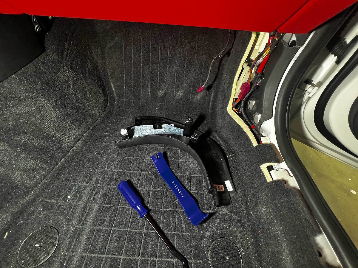
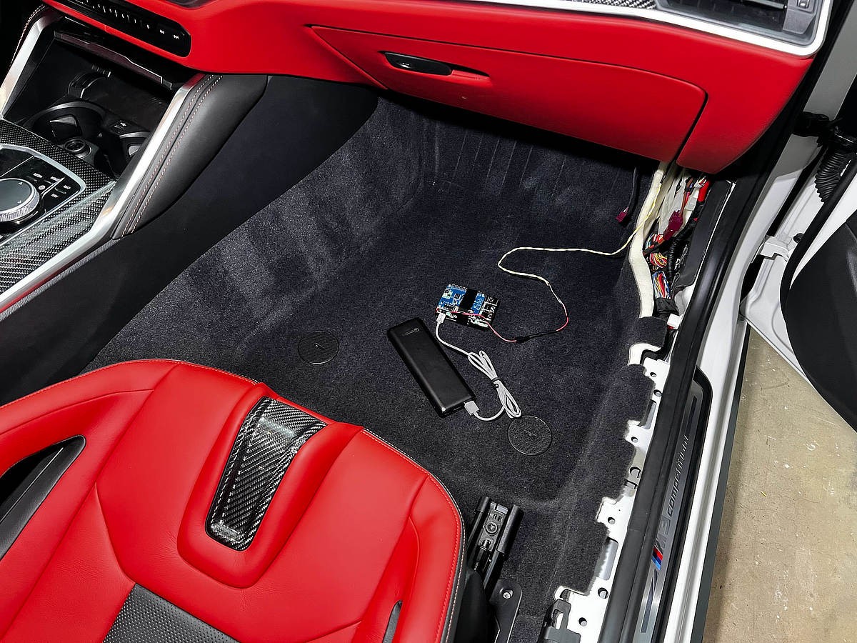
Step 1: Accessing the PT-CAN Bus on your BMW G8x
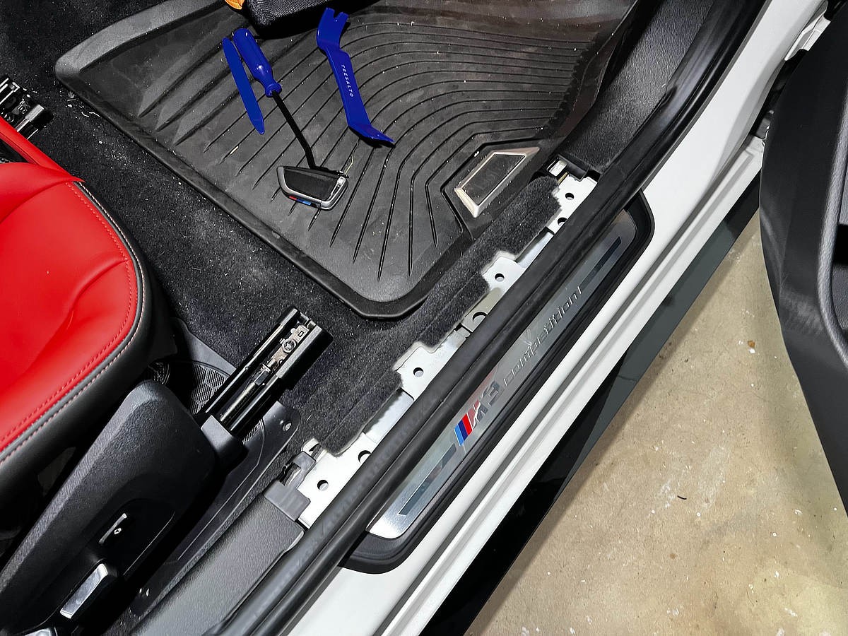
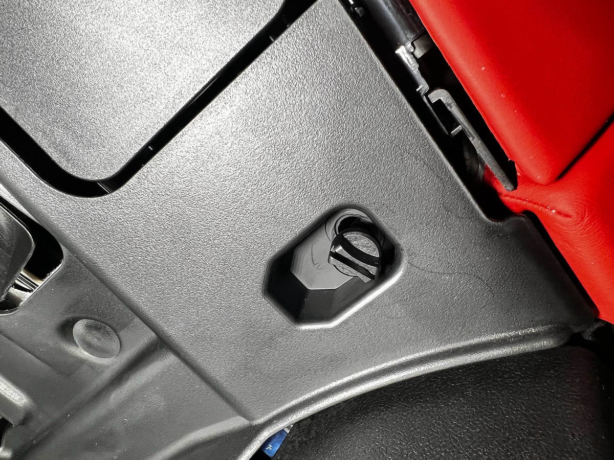
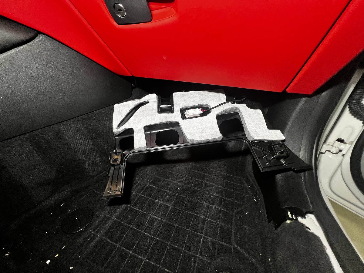
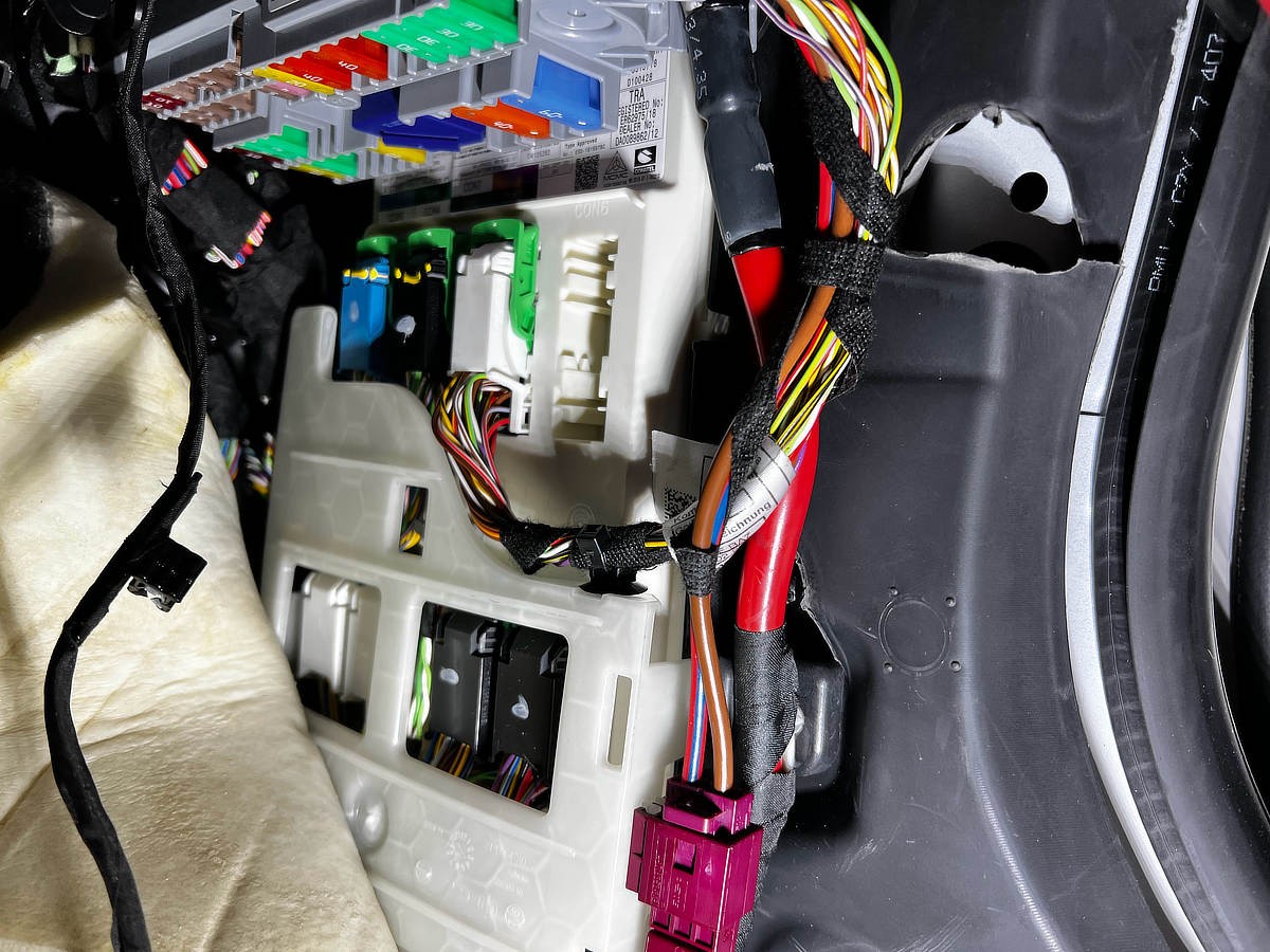
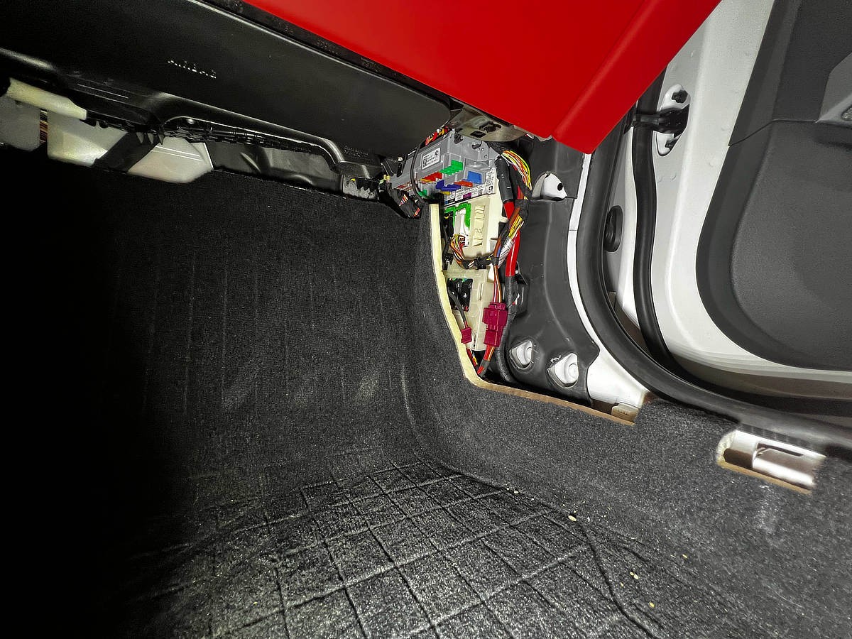
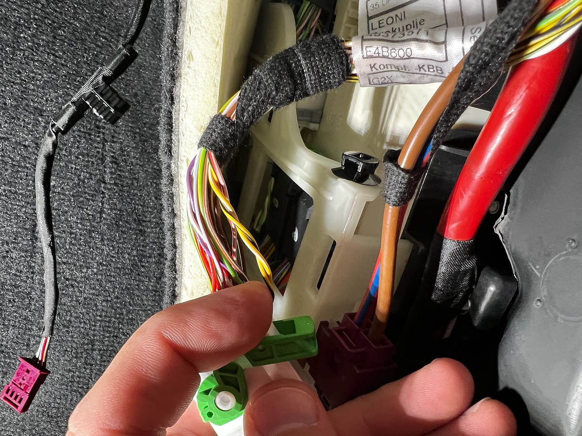
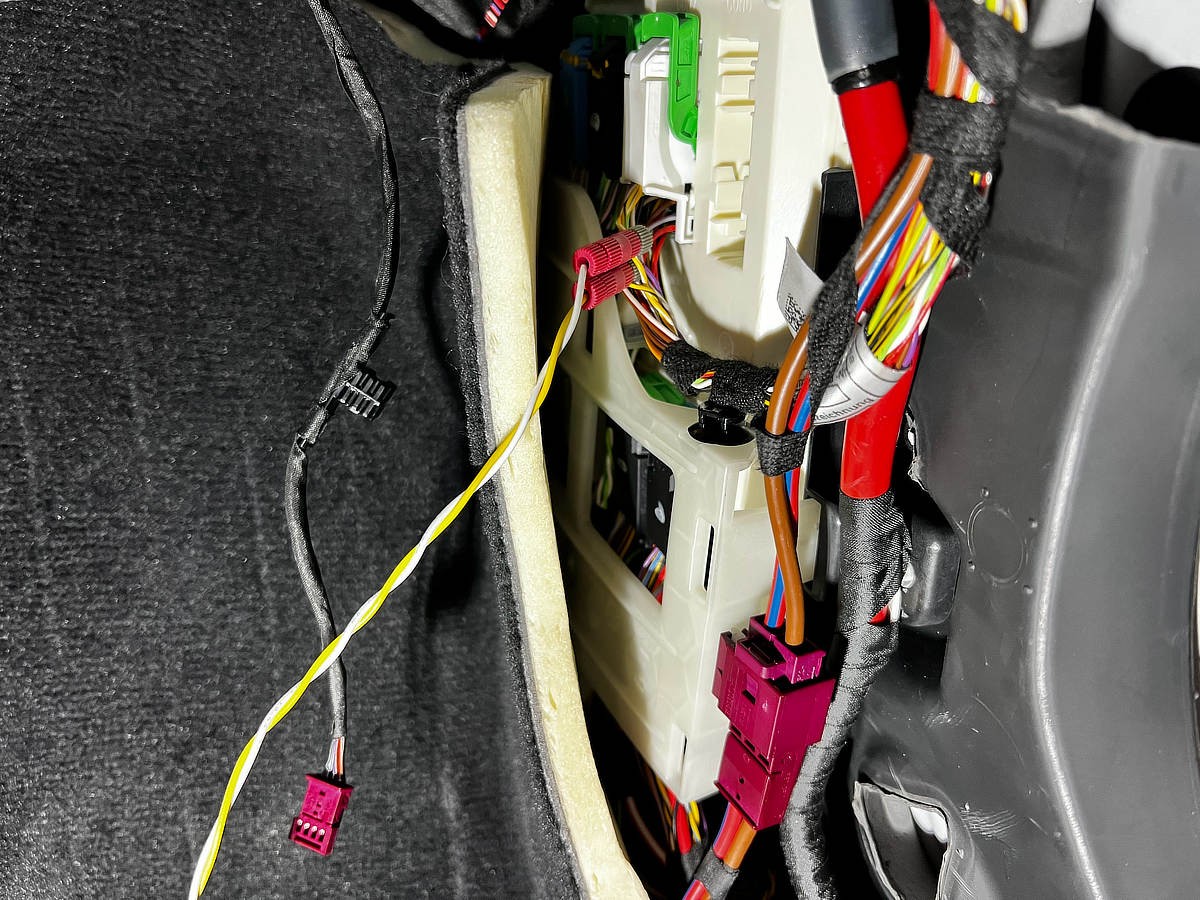
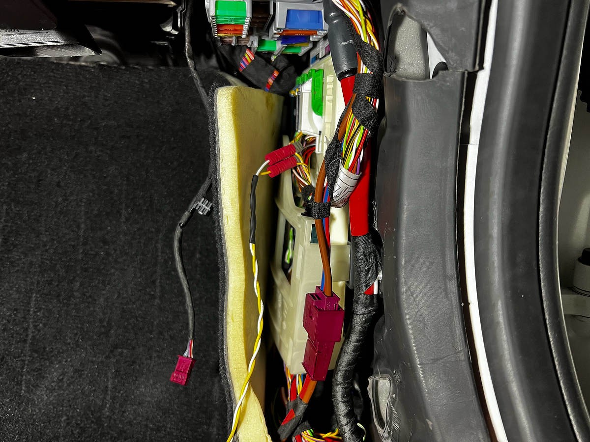
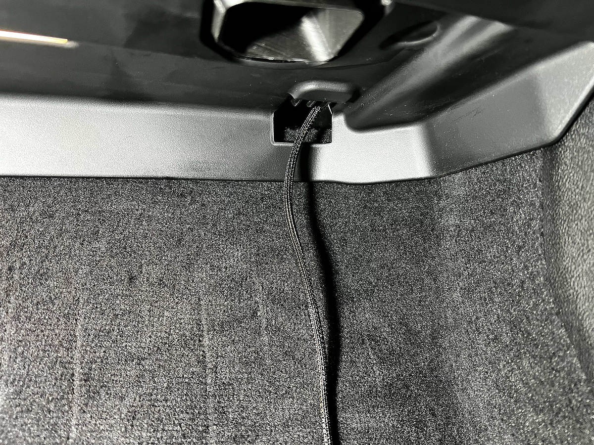
The first crucial step is to locate and tap into the PT-CAN (Powertrain CAN-bus) within your BMW G8x. A convenient access point is often found in the passenger side footwell. CAN-bus wires are easily identifiable as twisted pairs, a standard practice to minimize electromagnetic interference and ensure signal integrity.
For a non-invasive connection, posi-tap connectors are ideal. They allow you to tap into the existing wires without cutting or altering the factory wiring harness, preserving your BMW’s electrical system warranty and integrity. Using JST connectors further simplifies the setup, enabling easy connection and disconnection of your CAN-bus device.
CAN-bus Wire Color Coding (Typical BMW Standard):
- CAN High: Yellow/White
- CAN Low: Yellow/Black
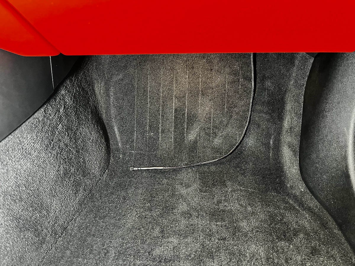
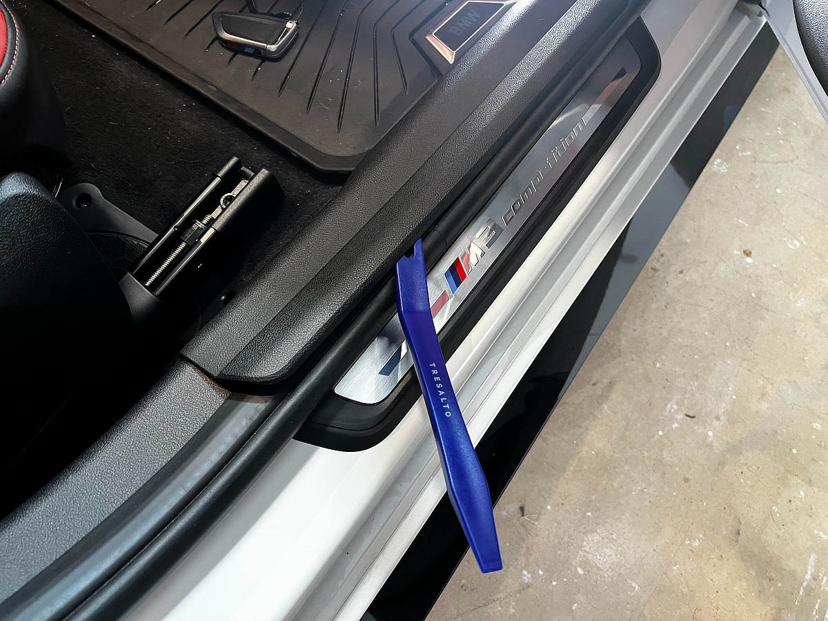 Passenger side footwell CAN-bus access point in a BMW G8x
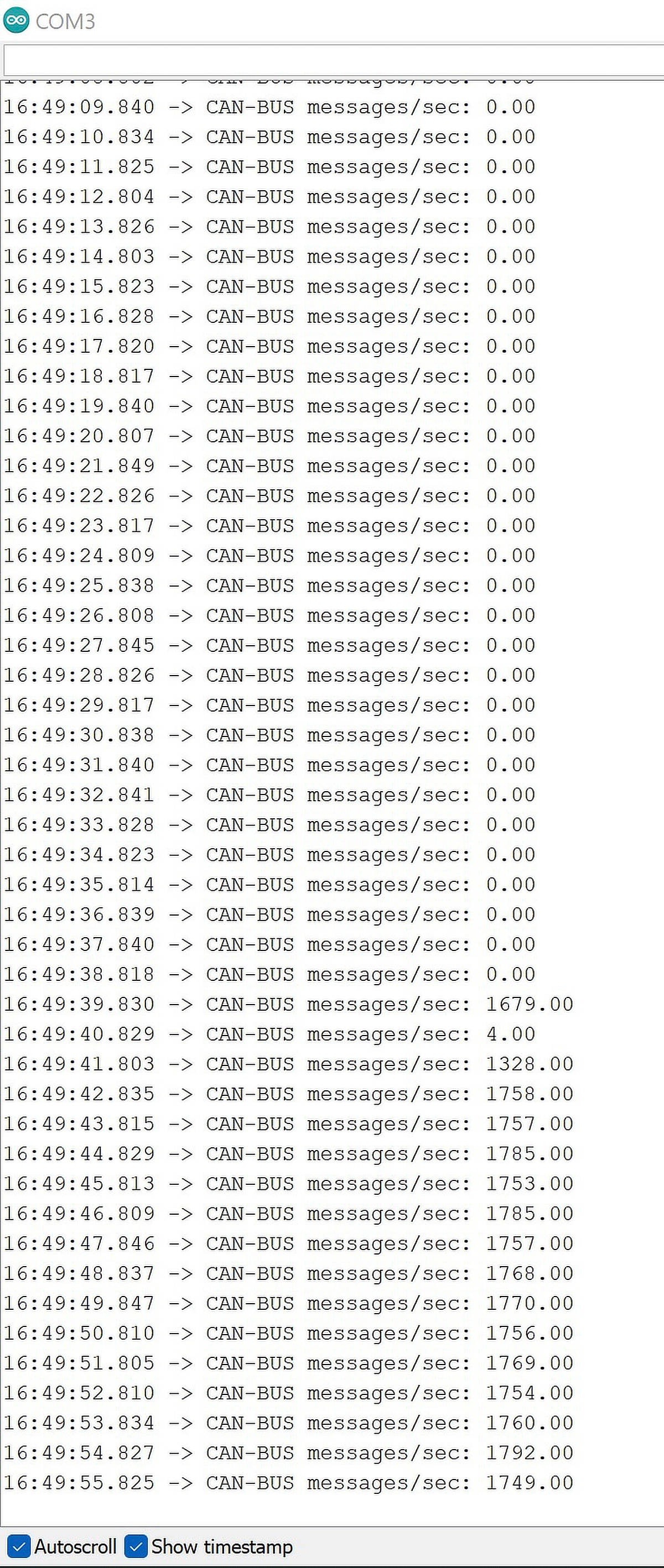
With a basic connection to the PT-CAN bus, you can expect to see a high volume of CAN frames transmitted per second – in this case, around 1750 frames per second were observed. This data rate, while seemingly high, translates to approximately 20 kbps of message traffic on a 500 kbps CAN-bus, indicating a significant amount of available bandwidth for data acquisition.
 Close-up of twisted pair CAN-bus wires in BMW
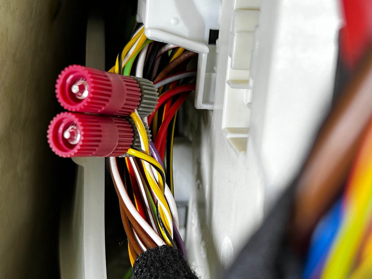
 Posi-tap connectors for non-invasive CAN-bus tapping
 JST connectors for easy device connection/disconnection
 Tapping into CAN-bus wires with posi-taps
 Securing posi-tap connections
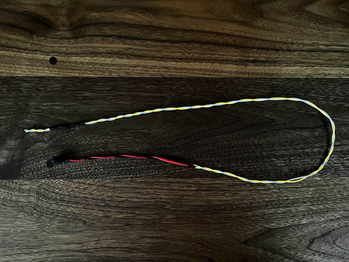
 Adding wires and JST connector to the CAN-bus tap
 Twisting CAN-bus wires for signal integrity
 Neatly wiring the CAN-bus connection
 Preparing to cover the CAN-bus connection
 Covering the CAN-bus connection for protection
 Finished CAN-bus tap with JST connector
 Adding wire to JST connector
 Soldering JST connector wires
 Heat shrinking JST connector wires
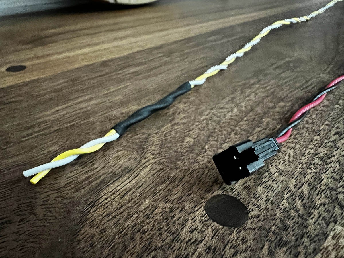
 Close up of twisted wires with JST connector
 JST connector ready for connection
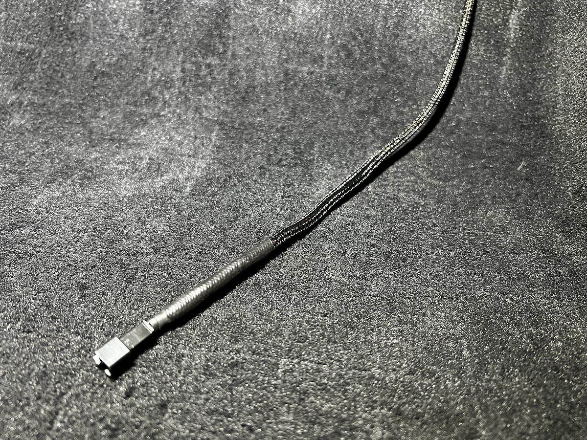 Finished JST connector ready for CAN-bus device
Step 2: Decoding BMW G8x CAN-bus Data
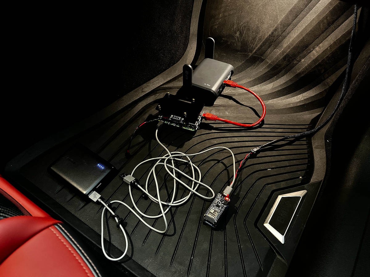
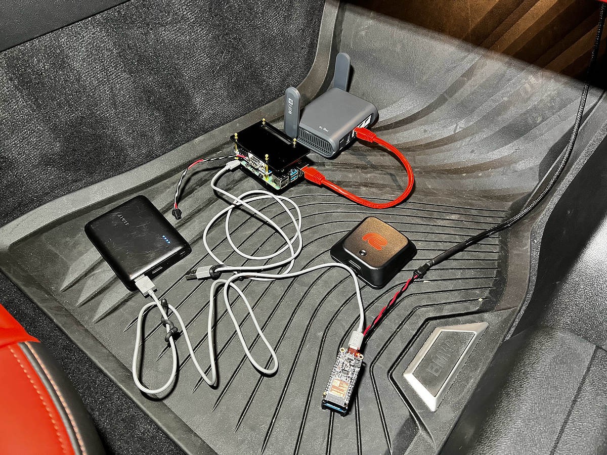
Automotive manufacturers typically do not publicly release CAN-bus data specifications, making reverse engineering necessary. To decipher the data transmitted on the PT-CAN bus of the G8x, a Raspberry Pi (model 3 or 4) equipped with a PiCan2 hat is an excellent tool. This setup allows for capturing and logging CAN-bus traffic using utilities like candump and cansniff for offline analysis.
This data decoding phase is often the most time-consuming aspect. It involves analyzing captured CAN frames to identify messages of interest and determine their structure and meaning. While a detailed explanation of CAN-bus reverse engineering is beyond the scope of this guide, the key is iterative analysis and correlation of CAN data with vehicle behavior.
The effort invested in decoding yields a wealth of valuable data. The following parameters have been successfully decoded on the G8x PT-CAN bus:
- RPM: 100Hz
- Throttle Position: 100Hz
- Gear: 50Hz
- Longitudinal Acceleration: 50Hz
- Lateral Acceleration: 50Hz
- Yaw Rate: 50Hz
- Vehicle Speed: 50Hz
- Wheel Speed (Individual Wheels): 50Hz
- Battery Voltage: 10Hz
- Air Temperature: 1Hz
- Steering Angle: 5Hz
- Coolant Temperature: ~5Hz
- Engine Oil Temperature: ~5Hz
- Gearbox Shift Speed (S1, S2, S3 Modes): 10Hz
Progress is also being made in identifying:
- Front Brake Pressure
- Rear Brake Pressure
Currently, the following data points are still under investigation:
- Intake Temperature
- Fuel Level
Notably, gear information is available from multiple CAN IDs, with one providing 50Hz updates and another at 1Hz but with instantaneous updates upon gear changes. The latter is preferred for telemetry applications as it minimizes CAN-bus and Bluetooth LE traffic without compromising accuracy.
Step 3: Assembling the ESP32 Arduino CAN-bus Device
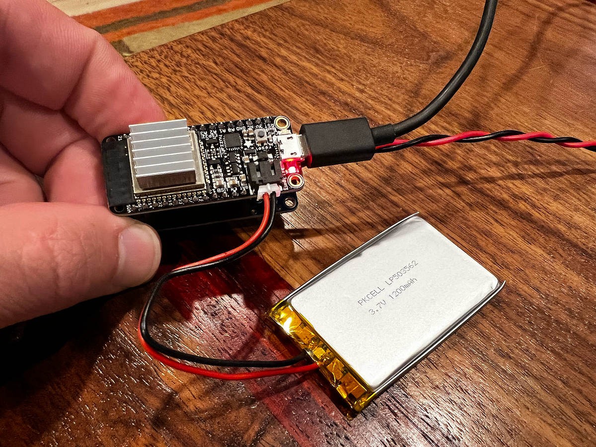
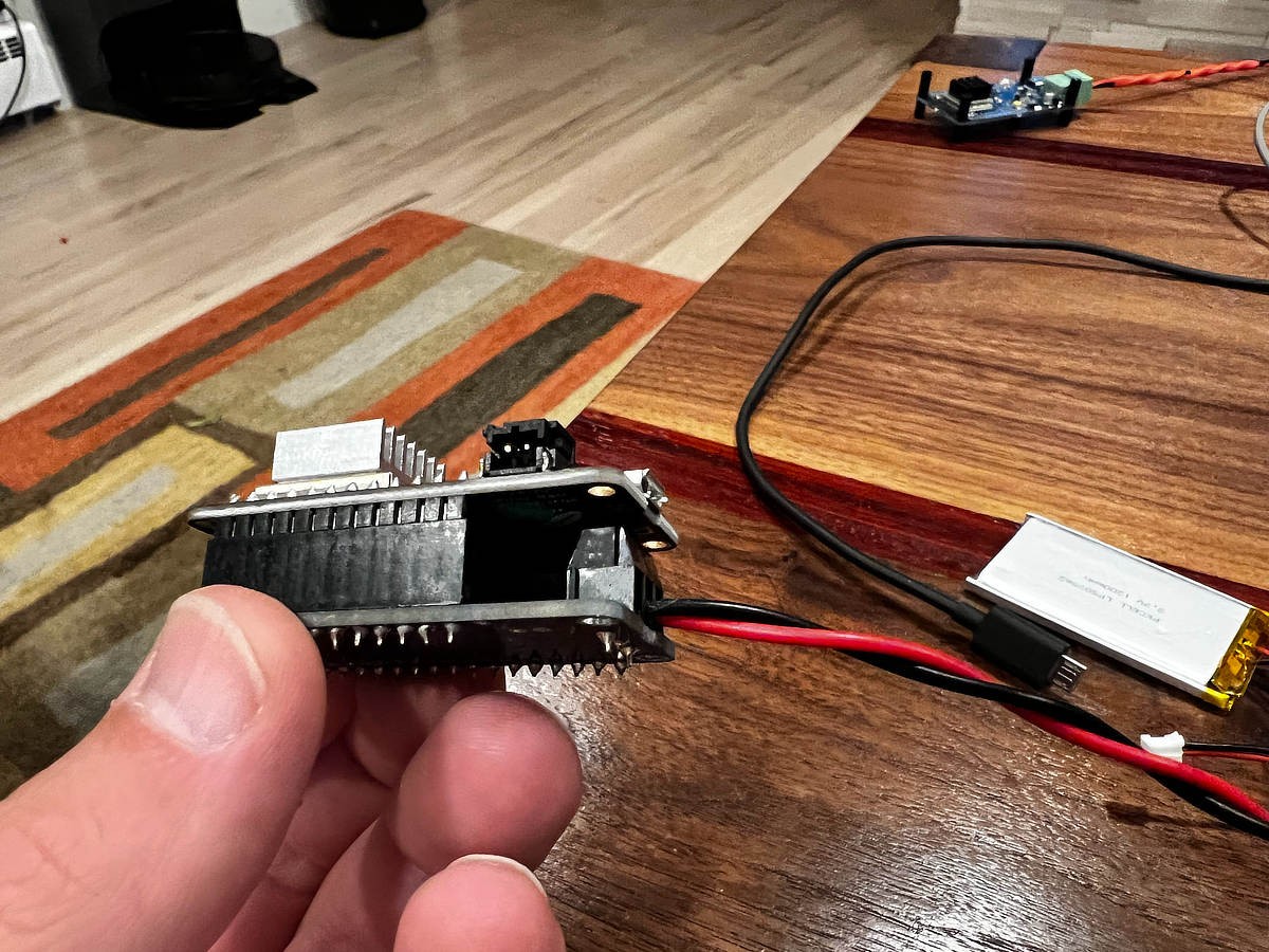
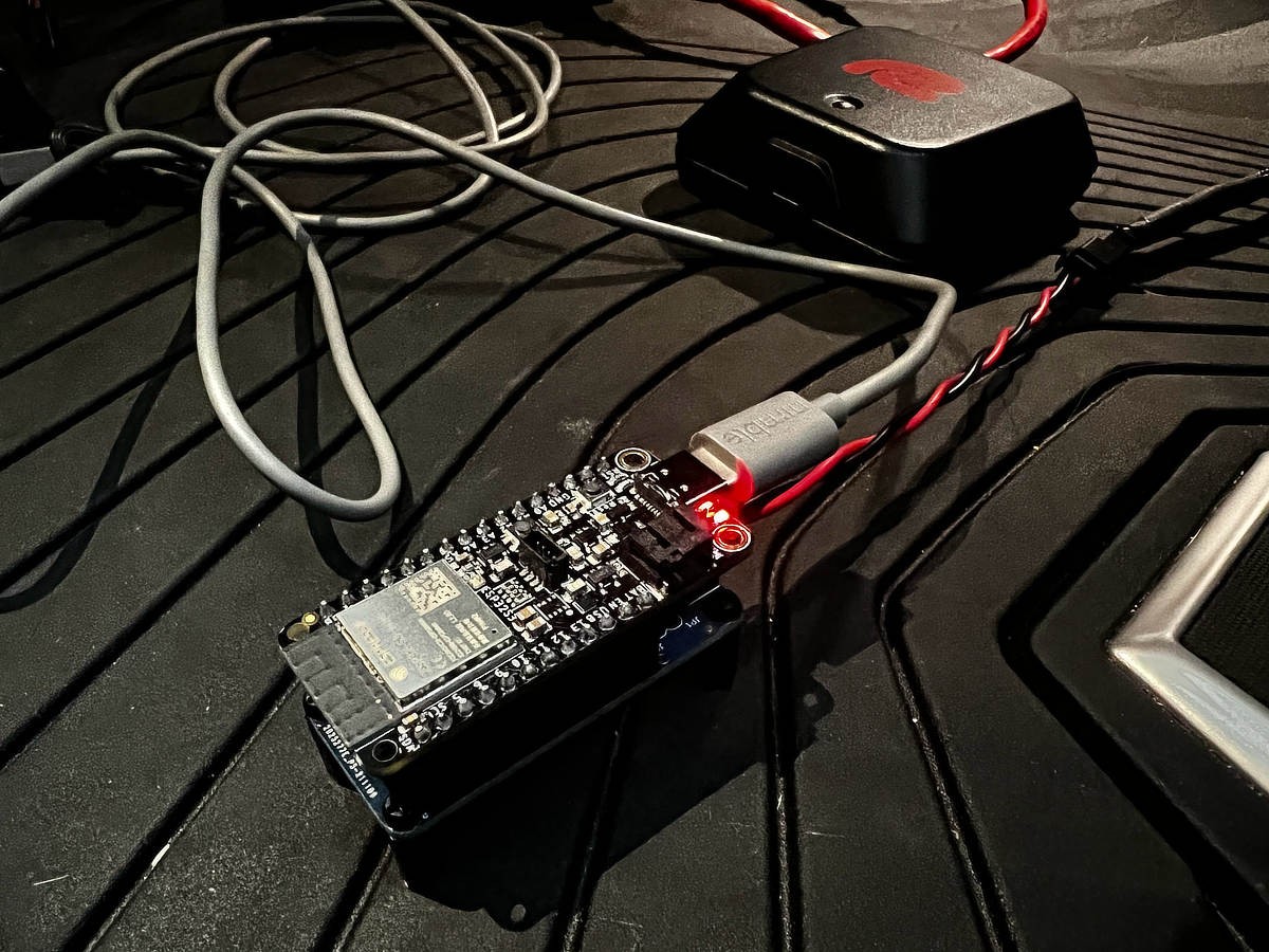
For the DIY CAN-bus interface, the Adafruit Feather S3 ESP32 board is a robust and feature-rich choice. Its key advantages include Bluetooth LE 5.0 for efficient wireless data transmission, a built-in battery connector for portable operation, and USB-C for convenient charging and serial communication. While older ESP32 boards with Bluetooth 4.0 could suffice, the Feather S3 offers future-proofing and enhanced connectivity.
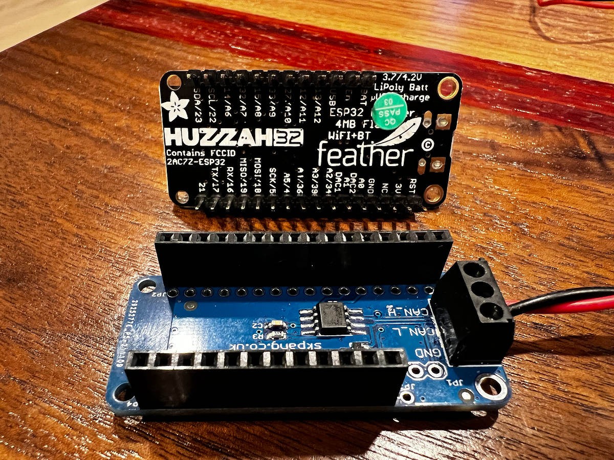
To interface the ESP32 with the CAN-bus, a CAN-bus Transceiver FeatherWing is used. This combination creates a compact and integrated CAN-bus interface. While the ESP32 chip itself incorporates a CAN controller, an external transceiver is necessary to handle the physical CAN-bus signaling levels.
Assembly is straightforward, primarily involving soldering the FeatherWing to the Feather ESP32 board. Despite the transceiver only requiring a few pins, soldering all pins ensures a mechanically robust and reliable connection, even for those with limited Arduino or electronics experience. Enclosing the assembled device in a 3D-printed case will further enhance its durability and portability.
 Adafruit Feather S3 ESP32 board
 CAN-bus Transceiver FeatherWing for ESP32
 Assembling ESP32 and CAN-bus FeatherWing
 Soldering pins on the ESP32 and FeatherWing
 Soldered ESP32 and CAN-bus FeatherWing
 Close-up of soldered connections
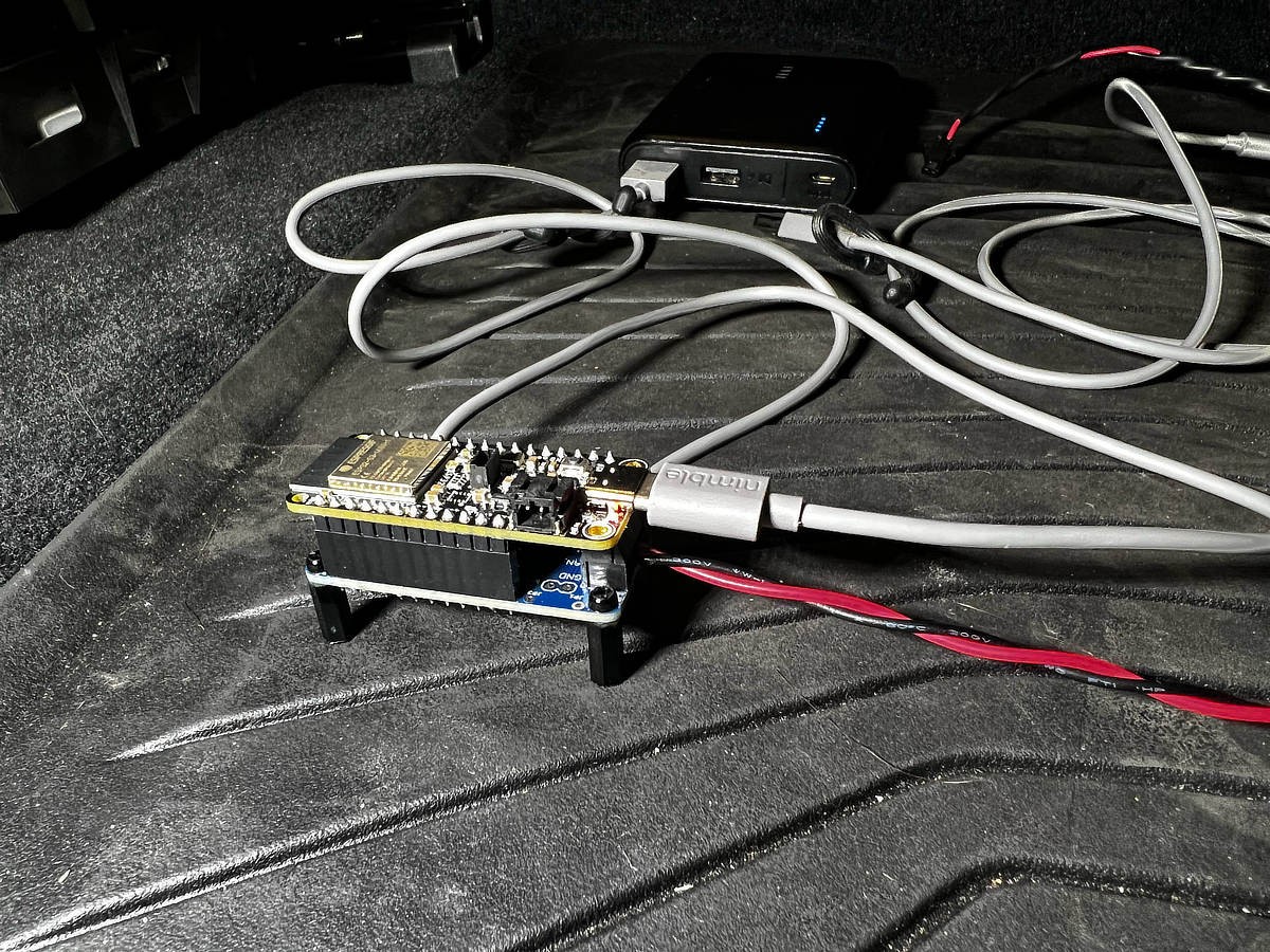 Assembled ESP32 CAN-bus device
Step 4: Configuring RaceChrono for CAN-bus Input
RaceChrono stands out as a leading track day software, particularly for DIY enthusiasts seeking CAN-bus integration. Compared to alternatives like TrackAddict and Harry’s Laptimer, RaceChrono offers superior flexibility and customization, especially for custom hardware interfaces.
Once the ESP32 CAN-bus device is operational and paired via Bluetooth LE, RaceChrono Pro allows you to easily add it as a “Bluetooth LE CAN-bus device” within the “External Devices” settings.
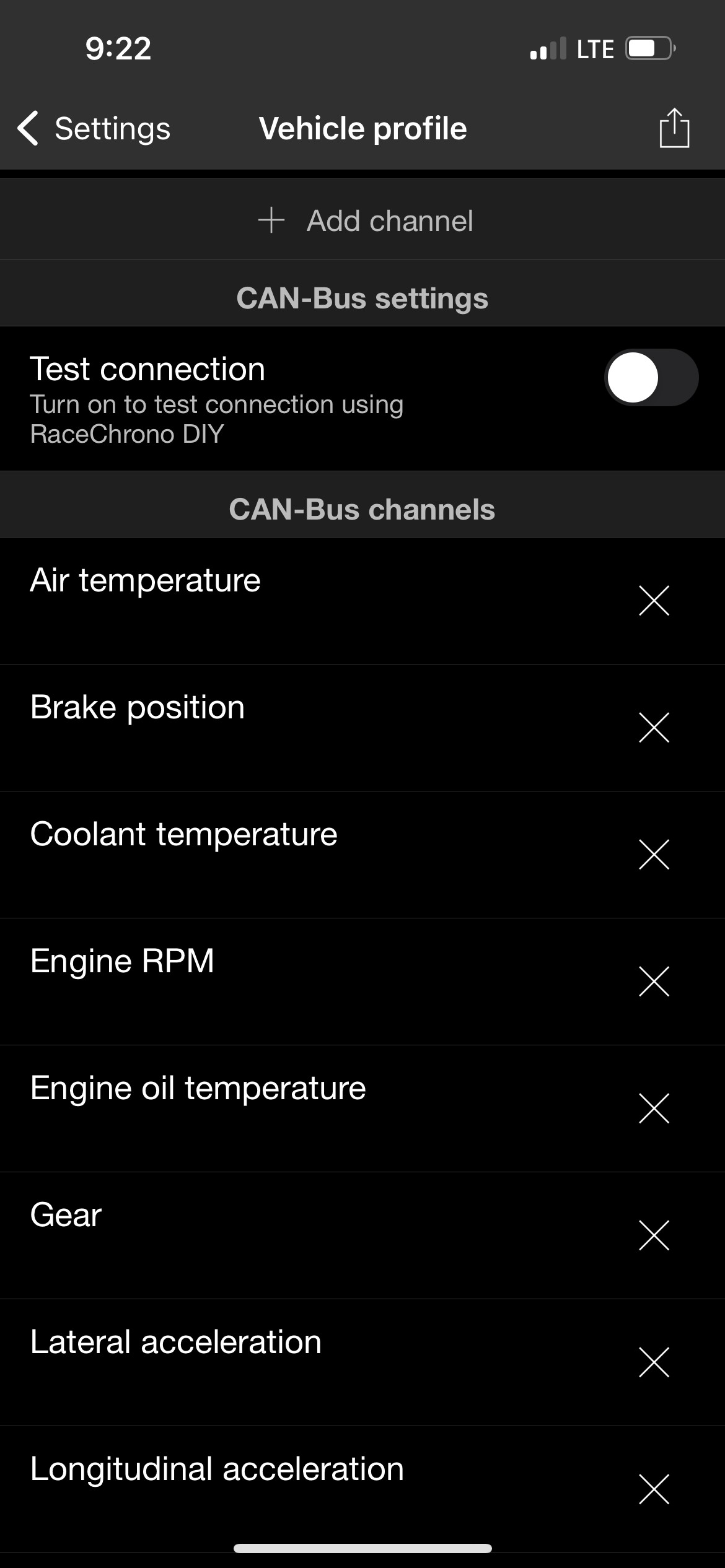
After adding the device, you can define custom channels within RaceChrono. This involves mapping raw CAN-bus data to human-readable values using formulas. The provided Google Sheet (https://docs.google.com/spreadsheets…it?usp=sharing) includes a column with RaceChrono formulas to facilitate this process, streamlining the setup.
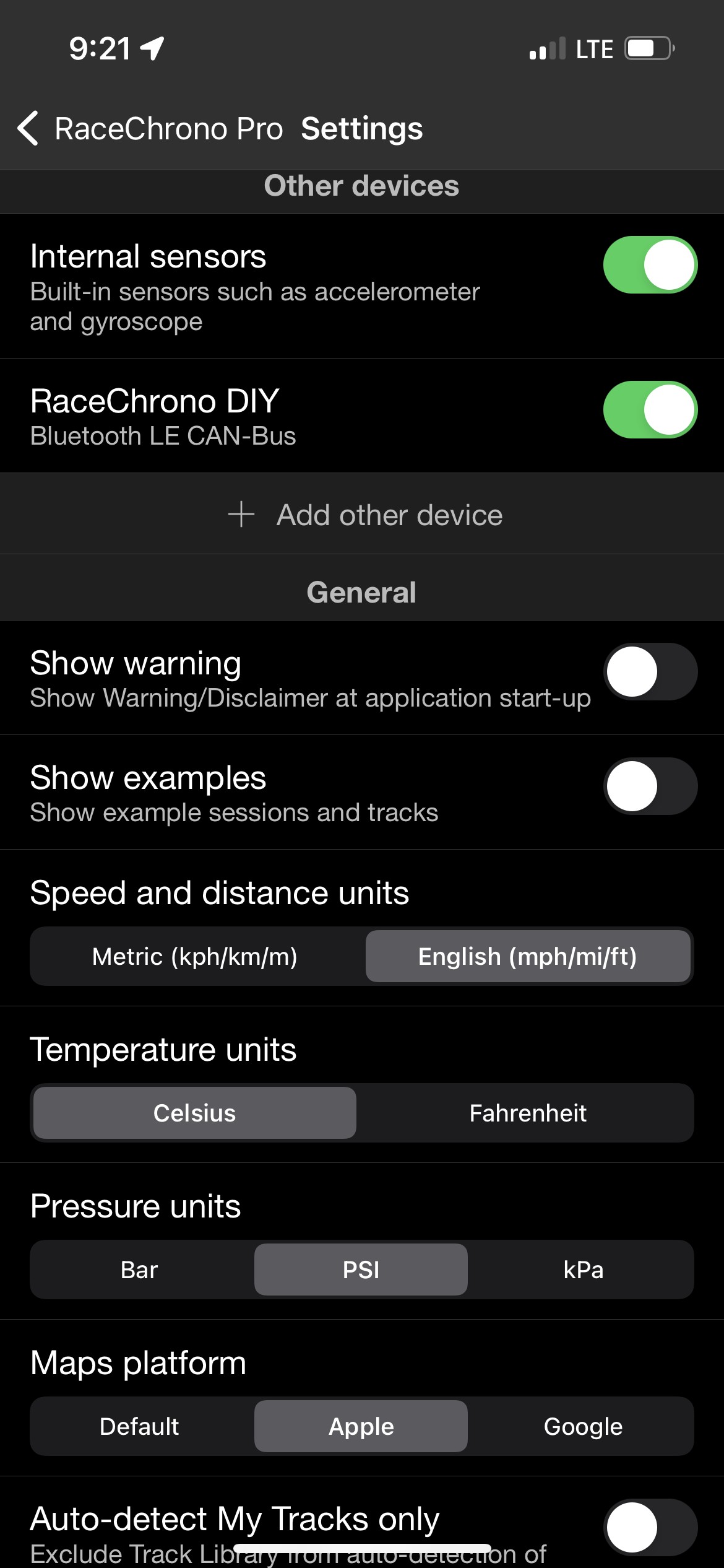 RaceChrono settings for external devices
 Adding a Bluetooth LE CAN-bus device in RaceChrono
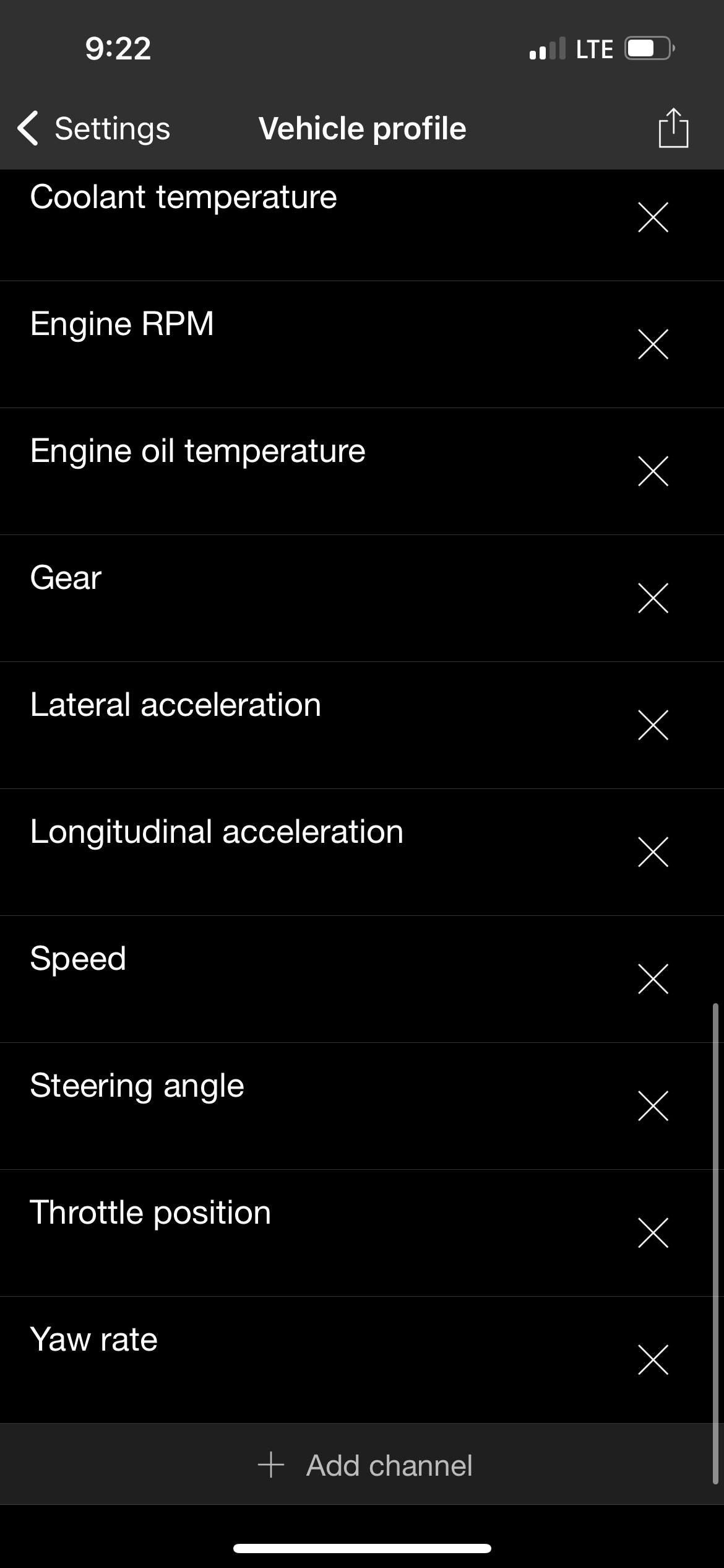 RaceChrono channel configuration with formulas
Step 5: ESP32 Device Firmware (Source Code)
To optimize performance, especially for read-only track telemetry applications, a custom CAN-bus driver stack was developed for the ESP32. Further optimization is planned for the Bluetooth LE driver, as the stock Arduino BLE libraries may present a performance bottleneck in high-data-rate scenarios.
The source code for the ESP32 firmware is available on GitHub: https://github.com/joeroback/racechrono-canbus
Conclusion
Accessing CAN-bus data on your BMW G8x unlocks a wealth of performance information, far exceeding the data available through standard OBD-II ports, which are often limited in modern vehicles like the G8x. While OBD-II and tools designed for 2011 F20 BMW models might offer basic diagnostics, they lack the depth and speed of CAN-bus for real-time performance telemetry. This DIY approach provides a powerful, customizable, and cost-effective solution for track day enthusiasts and anyone interested in advanced vehicle data analysis. By combining readily available hardware with open-source software and community knowledge, you can create a sophisticated telemetry system tailored to your BMW G8x and RaceChrono, taking your track day data analysis to the next level.
(Full Imgur Album of Project Images: View post on imgur.com)