Diagnosing issues with your 2013 Ford F-150 often starts with connecting an OBD2 scanner to the diagnostic port. However, if your scanner isn’t powering up or communicating with your truck’s computer, a blown fuse might be the culprit. Locating the correct fuse for the OBD2 port is crucial for quick troubleshooting and repair. This guide will walk you through finding the 2013 Ford F-150 OBD2 fuse location and understanding the fuse box diagrams to resolve potential diagnostic communication problems.
Your 2013 Ford F-150, like the 2014 model, is equipped with two primary fuse boxes. Knowing where these are located is the first step in identifying and checking the OBD2 fuse. These fuse panels are designed to protect your vehicle’s electrical circuits from overloads, and the OBD2 system is no exception.
The two main fuse box locations in your 2013 Ford F-150 are:
- Passenger Compartment Fuse Panel: Located inside the cabin of your F-150.
- Power Distribution Box: Situated in the engine compartment.
Let’s explore each of these locations in detail to help you pinpoint the fuse related to your OBD2 port.
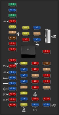
 2014 Ford F-150 fuse box diagram Passenger Compartment Fuse Panel
The Passenger Compartment Fuse Panel is typically the first place to check for fuses related to interior electronics and diagnostic systems. In the 2014 Ford F-150, and likely similarly in the 2013 model, this panel is often located beneath the dashboard on the driver’s side. You may need to look under the steering wheel and possibly remove a small access panel to fully expose the fuse box.
While the diagram provided is for a 2014 model, fuse box layouts for vehicles within the same generation often remain very similar. Consulting your 2013 Ford F-150 owner’s manual is always recommended for the most accurate fuse designations, but the 2014 diagram can serve as a highly indicative reference.
According to the 2014 diagram for the Passenger Compartment Fuse Panel, several fuses could potentially be linked to the OBD2 port, as it’s part of the vehicle’s data communication network. Fuses related to the Powertrain Control Module (PCM), data link connector, or instrument cluster could indirectly affect the OBD2 port’s functionality if they are blown.
Here’s a table detailing the fuses in the Passenger Compartment Fuse Panel of a 2014 Ford F-150. While referencing this for your 2013 model, always double-check with your owner’s manual for precise assignments.
| Type | No. | Description |
|---|---|---|
| Fuse MINI 30A | 1 | Driver side front window |
| Fuse MINI 15A | 2 | SYNC , Display module (8 inch) |
| Fuse MINI 30A | 3 | Passenger side front window |
| Fuse MINI 10A | 4 | Interior lamps |
| Fuse MINI 20A | 5 | Memory module |
| Fuse MINI 5A | 6 | Not used (spare) |
| Fuse MINI 7.5A | 7 | Power mirror switch, Memory seat module |
| Fuse MINI 10A | 8 | Not used (spare) |
| Fuse MINI 10A | 9 | Radio display, GPS module, Electric finish panel module |
| Fuse MINI 10A | 10 | Run/accessory relay |
| Fuse MINI 10A | 11 | Instrument cluster |
| Fuse MINI 15A | 12 | Interior lighting, Puddle lamps, Backlighting, Cargo lamp |
| Fuse MINI 15A | 13 | Right turn signals/stop lamps View problems with the brake light fuse… |
| Fuse MINI 15A | 14 | Left turn signals/stop lamps View problems with the brake light fuse… |
| Fuse MINI 15A | 15 | Reverse lights, High-mounted stop lamp View problems with the brake light fuse… |
| Fuse MINI 10A | 16 | Right low-beam headlamp View problems with the headlight fuse… |
| Fuse MINI 10A | 17 | Left low-beam headlamp View problems with the headlight fuse… |
| Fuse MINI 10A | 18 | Brake-shift interlock, Keypad illumination, Powertrain control module wake-up, Passive anti-theft system |
| Fuse MINI 20A | 19 | Audio amplifier |
| Fuse MINI 20A | 20 | Power door locks |
| Fuse MINI 10A | 21 | Not used (spare) |
| Fuse MINI 20A | 22 | Horn View problems with the horn fuse… |
| Fuse MINI 15A | 23 | Steering wheel control module |
| Fuse MINI 15A | 24 | Datalink connector, Steering wheel control module |
| Fuse MINI 15A | 25 | Not used (spare) |
| Fuse MINI 5A | 26 | Radio frequency module |
| Fuse MINI 20A | 27 | Not used (spare) |
| Fuse MINI 15A | 28 | Ignition switch |
| Fuse MINI 20A | 29 | Radio View problems with the radio fuse… |
| Fuse MINI 15A | 30 | Front parking lamps |
| Fuse MINI 5A | 31 | Brake on/off –Instrument panel, Engine |
| Fuse MINI 15A | 32 | Delay/accessory –moonroof, power windows, locks, Automatic dimming mirror/Compass, Trailer tow power telescope mirrors |
| Fuse MINI 10A | 33 | Rear heated seats |
| Fuse MINI 10A | 34 | Reverse sensing system, 4×4 switch, Rear video, Off-road indicator [SVT Raptor], Front video [SVT Raptor], Camera splice module [SVT Raptor] |
| Fuse MINI 5A | 35 | Hill descent switch [SVT Raptor] |
| Fuse MINI 10A | 36 | Restraint control module, Occupant classification system module |
| Fuse MINI 10A | 37 | Trailer brake control |
| Fuse MINI 10A | 38 | Delayed accessory –110-volt power point, Radio View problems with the radio fuse… |
| Fuse MINI 15A | 39 | High-beam headlamps View problems with the headlight fuse… |
| Fuse MINI 10A | 40 | Rear park lamps |
| Fuse MINI 7.5A | 41 | Passenger airbag deactivation indicator, Auxiliary switch [SVT Raptor] |
| Fuse MINI 5A | 42 | Overdrive cancel switch |
| Fuse MINI 10A | 43 | Not used (spare) |
| Fuse MINI 10A | 44 | Not used (spare) |
| Fuse MINI 5A | 45 | Not used (spare) |
| Fuse MINI 10A | 46 | Climate controls module |
| Fuse MINI 15A | 47 | Fog lamps, Exterior mirror turn signals View problems with the fog light fuse… |
| Circuit breaker ATO | 48 | Power windows, Power sliding back window |
| Relay | 49 | Delayed accessory |
Looking at the table, Fuse 24 (15A), labeled “Datalink connector, Steering wheel control module,” is a prime candidate for the OBD2 fuse location in the Passenger Compartment Fuse Panel. The “Datalink connector” is another term for the OBD2 port. Therefore, if your OBD2 scanner is not working, checking this fuse should be one of your first steps.
 2014 Ford F-150 fuse box diagram Power Distribution Box
The Power Distribution Box, located under the hood, generally houses fuses and relays for high-power systems in your 2013 Ford F-150, such as the engine, transmission, and braking systems. While less likely to directly house the OBD2 port fuse, it’s still worth understanding its layout in case related issues arise.
Again, while this diagram is for the 2014 F-150, the Power Distribution Box layout is likely to be similar for the 2013 model year. Always refer to your 2013 owner’s manual for the definitive fuse chart.
Below is the fuse and relay listing for the Power Distribution Box of a 2014 Ford F-150.
| Type | No. | Description |
|---|---|---|
| Relay | 1 | Powertrain control module [3.7L, 5.0L and 6.2L engines] |
| Relay | 2 | Starter View problems with the starter relay… |
| Relay | 3 | Blower motor |
| Relay | 4 | Rear window defroster |
| Relay | 5 | Electric fan (high speed) View problems with the cooling fan relay… |
| Relay | 6 | Trailer tow park lamp |
| Relay | 7 | Run/start View problems with the starter relay… |
| Relay | 8 | Fuel pump View problems with the fuel pump relay… |
| Relay | 9 | Trailer tow battery charger |
| Relay | 10 | Powertrain control module [3.5L engine] |
| Fuse FMX/JCase 30A | 11 | Power running board motors |
| Fuse FMX/JCase 40A | 12 | Electric fan [3.7L, 5.0L] View problems with the cooling fan fuse… |
| Fuse FMX/JCase 50A | 12 | Electric fan [3.5L, 6.2L with max trailer tow, SVT Raptor] View problems with the cooling fan fuse… |
| Fuse FMX/JCase 30A | 13 | Starter relay power View problems with the starter fuse… |
| Fuse FMX/JCase 30A | 14 | Passenger power seat |
| Fuse FMX/JCase 40A | 15 | Electric fan [3.7L, 5.0L] View problems with the cooling fan fuse… |
| Fuse FMX/JCase 50A | 16 | Electric fan [3.5L, 6.2L with max trailer tow, SVT Raptor] View problems with the cooling fan fuse… |
| Fuse FMX/JCase 20A | 16 | High-intensity discharge headlamp – passenger side View problems with the headlight fuse… |
| Fuse FMX/JCase 30A | 17 | Trailer brake control |
| Fuse FMX/JCase 30A | 18 | Auxiliary switch 1 [SVT Raptor] |
| Fuse FMX/JCase 30A | 19 | Auxiliary switch 2 [SVT Raptor] |
| Fuse FMX/JCase 20A | 20 | 4×4 module (electronic shift) |
| Fuse FMX/JCase 30A | 21 | Trailer tow battery charge relay power |
| Fuse FMX/JCase 20A | 22 | Auxiliary power point (instrument panel) View problems with the cigarette lighter fuse… |
| Relay | 23 | Air conditioner clutch View problems with the air conditioning relay… |
| Fuse MINI 10A | 26 | Powertrain control module –keep alive power and relay coil, canister vent solenoid [3.7L, 5.0L and 6.2L engines] |
| Fuse MINI 20A | 27 | Fuel pump relay power View problems with the fuel pump fuse… |
| Fuse MINI 10A | 28 | Auxiliary switch 4 [SVT Raptor] |
| Fuse MINI 10A | 29 | 4×4 integrated wheel end solenoid |
| Fuse MINI 10A | 30 | Air conditioner clutch relay power View problems with the air conditioning fuse… |
| Fuse MINI 15A | 31 | Run/start relay power View problems with the starter fuse… |
| Fuse FMX/JCase 40A | 32 | Rear window defroster relay power, Heated mirror relay power |
| Fuse FMX/JCase 40A | 33 | 110-volt AC power point |
| Fuse FMX/JCase 40A | 34 | Powertrain control module relay power [3.7L, 5.0L and 6.2L engines] |
| Fuse FMX/JCase 50A | 34 | Powertrain control module relay power [3.5L engine] |
| Fuse FMX/JCase 20A | 35 | High-intensity discharge headlamps – driver side View problems with the headlight fuse… |
| Fuse FMX/JCase 30A | 36 | Roll stability control / Anti-lock brake system |
| Relay | 37 | Trailer tow left stop/turn |
| Relay | 38 | Trailer tow right stop/turn |
| Relay | 39 | Trailer tow back-up lamps |
| Relay | 40 | Electric fan View problems with the cooling fan relay… |
| Fuse MINI 15A | 41 | Front camera washer [SVT Raptor] |
| Fuse MINI 5A | 42 | Run/start relay coil View problems with the starter fuse… |
| Fuse MINI 15A | 43 | Trailer tow back-up lamp relay power |
| Fuse MINI 15A | 44 | Auxiliary switch 3 [SVT Raptor], Trailer tow power folding mirrors |
| Fuse MINI 10A | 45 | Alternator sensor [3.5L, 3.7L and 5.0L engines] |
| Fuse MINI 10A | 46 | Brake on/off switch |
| Fuse FMX/JCase 60A | 47 | Roll stability control / Anti-lock brake system module |
| Fuse FMX/JCase 20A | 48 | Moonroof View problems with the sunroof fuse… |
| Fuse FMX/JCase 30A | 49 | Wiper relay power |
| Fuse FMX/JCase 40A | 51 | Blower motor relay power |
| Fuse MINI 5A | 52 | Run/start –Electronic power assist steering, Blower relay coil |
| Fuse MINI 5A | 53 | Run/start –Powertrain control module |
| Fuse MINI 5A | 54 | Run/start –4×4 module, Back-up lamps, Roll stability control /Anti-lock brake system, Trailer tow battery charge relay coil, Rear window defroster relay coil, Front camera washer relay coil [SVT Raptor] |
| Fuse MINI 15A | 56 | Heated mirrors |
| Relay | 62 | Wiper motor |
| Fuse FMX/JCase 25A | 63 | Electric fan relay power View problems with the cooling fan fuse… |
| Fuse FMX/JCase 20A | 65 | Auxiliary power point (instrument panel) View problems with the cigarette lighter fuse… |
| Fuse FMX/JCase 20A | 66 | Auxiliary power point (inside center console) |
| Fuse FMX/JCase 20A | 67 | Trailer tow park lamps relay power |
| Fuse FMX/JCase 25A | 68 | 4×4 module, 4×2 elocker module |
| Fuse FMX/JCase 30A | 69 | Front heated or heated/cooled seats |
| Fuse FMX/JCase 20A | 71 | Heated rear seats |
| Fuse FMX/JCase 20A | 72 | Auxiliary power point (rear) |
| Fuse FMX/JCase 20A | 73 | Trailer tow stop/turn lamps relay power View problems with the tail light fuse… |
| Fuse FMX/JCase 30A | 74 | Driver power seat/memory module |
| Fuse MINI 15A | 75 | Powertrain control module –voltage power 1 [3.7L, 5.0L, 6.2L engines] |
| Fuse MINI 25A | 75 | Powertrain control module –voltage power 1 [3.5L engine] |
| Fuse MINI 20A | 76 | Powertrain control module –Voltage power 2: General powertrain components (Mass air flow/Intake air temp sensor – [3.7L, 5.0L, 6.2L engines](Canister vent solenoid – [3.5L engine] |
| Fuse MINI 10A | 77 | Powertrain control module –Voltage power 3 (Emission related powertrain components, Electric fan relays coil) View problems with the cooling fan fuse… |
| Fuse MINI 15A | 78 | Powertrain control module –Voltage power 4 –Ignition coils [3.5L, 3.7L, 5.0L engines] |
| Fuse MINI 20A | 78 | Powertrain control module –Voltage power 4 –Ignition coils [6.2L engine] |
| Fuse MINI 5A | 79 | Rain sensor |
| Relay | 85 | Electric fan (low speed) View problems with the cooling fan relay… |
While the Power Distribution Box may not directly contain a fuse labeled “OBD2” or “Datalink connector,” fuses powering the PCM are located here. For instance, Fuses 26, 75, 76, 77, and 78 in the Power Distribution Box are all related to the Powertrain Control Module. If the PCM is not receiving power due to a blown fuse in this box, it could indirectly prevent the OBD2 port from functioning.
Troubleshooting Steps for a Non-Functioning OBD2 Port in your 2013 Ford F-150:
- Locate the Passenger Compartment Fuse Panel: Refer to your 2013 Ford F-150 owner’s manual for the exact location, but it’s generally under the dashboard on the driver’s side.
- Identify Fuse 24 (Datalink Connector): Using your owner’s manual’s fuse diagram or the 2014 diagram as a guide, locate Fuse 24, which is designated for the “Datalink connector” (OBD2 port).
- Inspect Fuse 24: Carefully remove the fuse and check if the internal wire is broken or melted. A blown fuse will need replacement.
- Check PCM Related Fuses: If Fuse 24 is intact, investigate the Power Distribution Box under the hood. Examine fuses related to the Powertrain Control Module (PCM) as listed above (Fuses 26, 75, 76, 77, 78 in the 2014 diagram). A problem with PCM power can also disable the OBD2 port.
- Replace Blown Fuses: If you find any blown fuses, replace them with fuses of the exact same type and amperage rating.
- Test your OBD2 Scanner: After replacing any blown fuses, try connecting your OBD2 scanner again to see if it now powers up and communicates with your 2013 Ford F-150.
Important Notes:
- Always Consult Your Owner’s Manual: Fuse box diagrams and fuse assignments can vary slightly between model years and trim levels. Your 2013 Ford F-150 owner’s manual is the most accurate resource for your specific vehicle.
- Fuse Amperage: Never replace a fuse with one of a higher amperage rating. Doing so can damage your vehicle’s electrical system and create a fire hazard.
- Underlying Issues: If you repeatedly blow the OBD2 port fuse or PCM fuses, there is likely an underlying electrical problem in your 2013 Ford F-150 that needs professional diagnosis and repair. A short circuit or wiring issue could be overloading the fuse.
By systematically checking these fuse locations and diagrams, you can effectively troubleshoot and often resolve issues related to a non-functional OBD2 port in your 2013 Ford F-150, getting you back to diagnosing and maintaining your truck efficiently. If the problem persists after checking and replacing fuses, it’s recommended to consult a qualified automotive technician for further diagnosis.