Building a custom fuse block and integrating an OBD2 diagnostic port is a common task for automotive enthusiasts and those undertaking engine swaps or custom wiring projects. This guide will walk you through the process, focusing on using the 829-12110250 Obd2 connector and readily available parts to create a robust and functional system.
For those working on projects like LT1, LS1, or Vortec truck engine swaps, a reliable fuse block and accessible OBD2 port are crucial for system protection and diagnostics. Let’s delve into the components and steps required to assemble your own.
Parts Required for OBD2 Diagnostic Port Assembly
The foundation of our OBD2 port is the 829-12110250 connector from Mouser. This 16-pin plastic connector is the industry standard for OBD2 implementations. Here’s a breakdown of the parts you’ll need specifically for the OBD2 port:
| Part Description | Vendor | Part Number | Quantity Needed |
|---|---|---|---|
| OBD2 Port Plastic Connector, 16 Pin | Mouser | 829-12110250 | 1 |
| Terminals – for OBD2 port | Mouser | 829-12129373 | 4 |
| Terminal Lock – secures terminals | Mouser | 829-12160437 | 2 |
| Lamp (for check engine light) | AllElectronics | check lamps/indicators, inventory changes | 1 (optional) |
Key Component: 829-12110250 OBD2 Connector
The 829-12110250 OBD2 connector is central to this build. It ensures compatibility with standard OBD2 diagnostic tools and scanners. Sourcing quality terminals and terminal locks alongside this connector will guarantee secure and lasting connections within your OBD2 port.
Image alt text: Detailed view of components for building an OBD2 port, prominently featuring the 829-12110250 connector, along with individual terminals and terminal locking pieces.
Fuse Block and Relay Components
Beyond the OBD2 port, a fuse block is essential for protecting your electrical circuits, and relays are needed for controlling higher current devices. Here are the parts for this section:
| Part Description | Vendor | Part Number | Quantity Needed |
|---|---|---|---|
| Fuse Block Housing kit (terminals incl.) | RockAuto / Terminal Supply Co. | 85668 | 1 |
| Relay Socket | AllElectronics | SRLY-2 | 2 |
| Relay 30 Amp | AllElectronics | RLY-351 | 2 |
| Relay Terminal 14-18 AWG | Mouser | 571-42238-2 | 8 |
It’s worth noting that the Dorman part number 85668 fuse block kit, available from RockAuto or even through AUTOZONE, is a cost-effective option.
Image alt text: Display of fuse block components, showcasing the fuse block housing (Dorman 85668), along with relay sockets (SRLY-2) and assorted terminals, ready for assembly.
Fuse Block Wiring: Step-by-Step
When wiring the fuse block, it’s crucial to use appropriate gauge wiring and secure connections. The relay sockets from AllElectronics often come with pre-installed wires, but it’s recommended to replace these with wires suitable for your current demands. Always crimp and solder your connections for maximum reliability.
Image alt text: Illustrative close-up of the fuse block wiring stage, emphasizing the process of crimping and soldering terminals onto heavy gauge wires for robust electrical connections.
Image alt text: Visual guide demonstrating the insertion of terminals into the relay output leg and the placement of bussed fuse terminals into the designated slots within the fuse block.
Image alt text: Image confirming the secure seating of relay terminals and bussed fuse terminals inside the fuse block, showing they are correctly positioned and locked in place.
Image alt text: Wiring diagram highlighting the connection of the relay input terminal to a 12V+ battery source, which also provides constant power to the designated fuse within the assembled block.
Image alt text: Arrangement of pink wires consolidated for key-switched hot fuses, also incorporating a dedicated wire intended for the check engine light (MIL) circuit.
Image alt text: Illustration of an orange wire being integrated for continuous battery power to the PCM, along with a jumper wire connecting to the fuel pump relay input terminal.
Image alt text: Wiring setup depicting the grounding of relay coils, achieved with a jumper from relay to relay, alongside the fuel pump relay control wire originating from the PCM and connected to the relay coil terminal.
OBD2 Diagnostic Port Wiring Details
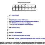
OBD2 port wiring is standardized for LS1 and Vortec truck PCMs. Here’s a typical configuration:
- Pin 2: Serial Data – Connects to the PCM.
- Pin 4 & 5: Ground – Pin 5 is typically sufficient, but some scan tools may require ground on Pin 4 as well.
- Pin 16: 12v+ Battery – Power source from the battery.
Specific to OBD2 LT1 (96-97):
- Pin 6: Diagnostic Request/Field Output Enable
- Pin 9: UART Serial Data
Note on 1995 LT1: While these used an OBD2 port, they were not fully OBD2 compliant and utilized Pin 9 for serial data instead of Pin 2.
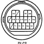
Image alt text: Wiring diagram detailing OBD2 port pin assignments and corresponding wire connections, specifically for integrating various vehicle systems and diagnostic capabilities.
By following these steps and utilizing quality components like the 829-12110250 OBD2 connector, you can construct a reliable fuse block and OBD2 diagnostic port for your custom automotive projects, ensuring both electrical system integrity and diagnostic accessibility.

