Maintaining the electrical system of your 1997 Ford Club Wagon 5.4L is crucial for its overall performance and reliability. Fuses play a vital role in protecting your vehicle’s electrical circuits from overloads, and knowing their locations is essential for quick troubleshooting and repairs. This guide provides a comprehensive overview of the fuse locations in your 1997 Ford Club Wagon, ensuring you can confidently address any electrical issues.
Your 1997 Ford E-150 Club Wagon is equipped with two primary fuse boxes. Understanding the function and location of each will streamline your diagnostic process when electrical problems arise. Let’s explore each fuse box in detail.
Understanding Fuse Boxes in Your 1997 Ford Club Wagon
For the 1997 Ford E-150 Club Wagon, you will find two distinct fuse box locations, each serving different electrical components:
- Instrument Panel Fuse Box: Located inside the vehicle, this fuse box is easily accessible and primarily controls circuits for interior functions, lighting, and essential vehicle controls.
- Power Distribution Box: Situated in the engine compartment, this box handles high-current fuses and relays that manage engine components, power accessories, and heavy-duty systems.
Knowing the location of these fuse boxes and the specific fuses they house is the first step in effectively diagnosing and resolving electrical problems in your 1997 Ford Club Wagon 5.4L.
Instrument Panel Fuse Box Diagram
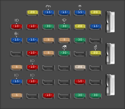
The instrument panel fuse box is conveniently located inside your 1997 Ford Club Wagon. This fuse box is responsible for protecting many of the interior and control circuits of your vehicle.
 1997 Ford E-150 instrument panel fuse box diagram
Diagram of the instrument panel fuse box for a 1997 Ford E-150, applicable to the 1997 Ford Club Wagon, highlighting fuse locations for interior and control circuits.
| Type | No. | Description |
|---|---|---|
| Fuse MINI 20A | 1 | 4WABS or RABS module |
| Fuse MINI 15A | 2 | 4WABS relay (coil), RABS (diode/resistor), instrument cluster, warning chime |
| Fuse MINI 15A | 3 | Headlamp switch, radio sense, rear radio control, Remote keyless entry module |
| Fuse MINI 15A | 4 | Power mirrors, modified vehicle, power locks w/RKE, Headlamp switch (dome), illuminated entry, Courtesy lamp switches, Radio (KAP), Cluster (KAP), warning chime |
| Fuse MINI 20A | 5 | Remote keyless entry module, power door lock switches, memory lock |
| Fuse MINI 10A | 6 | Brake shift interlock, speed control, daytime running light module |
| Fuse MINI 10A | 7 | Multi-function switch |
| Fuse MINI 30A | 8 | Noise supression capacitor, ignition coil positive feed, PCM relay diode/PCM power relay, fuel heater [diesel], glow plug relay [diesel] |
| Fuse MINI 30A | 9 | Wiper control module, wiper motor |
| Fuse MINI 20A | 10 | Headlamp switch (exterior lamps), Multi-function switch (flash-to-pass) |
| Fuse MINI 15A | 11 | Stoplight switch, brake pressure switch, multi-function switch |
| Fuse MINI 15A | 12 | Digital transmission range sensor (backup lamps), auxiliary battery relay |
| Fuse MINI 15A | 13 | A/C mode switch, blend door actuator |
| Fuse MINI 5A | 14 | Instrument cluster (air bag and charge indicator lamps) |
| Fuse MINI 5A | 15 | Trailer tow battery charge relay (coil) |
| Fuse MINI 30A | 16 | Power seats |
| Fuse MINI 10A | 19 | Air bag module |
| Fuse MINI 5A | 20 | Overdrive cancel switch |
| Fuse MINI 30A | 21 | Power windows |
| Fuse MINI 20A | 23 | Cigar lighter, data link connector |
| Fuse MINI 5A | 24 | Illuminated entry |
| Fuse MINI 10A | 25 | Left headlamp (low beam) |
| Fuse MINI 25A | 28 | Instrument panel power point |
| Fuse MINI 15A | 30 | Headlamps (high beam), Daytime running lamps (DRL), high beam indicator |
| Fuse MINI 10A | 31 | Right headlamp (low beam), Daytime running lamps (DRL) |
| Fuse MINI 10A | 34 | Digital transmission range sensor (start control) |
| Fuse MINI 5A | 36 | Panel illumination |
| Fuse MINI 10A | 38 | Air bag module |
| Fuse MINI 30A | 40 | Modified vehicle |
| Fuse MINI 30A | 41 | Modified vehicle |
This detailed diagram and table will assist you in identifying the correct fuse for circuits related to your instrument panel, lighting, and various control modules within the cabin of your 1997 Ford Club Wagon.
Power Distribution Box Diagram
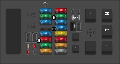
The power distribution box, located under the hood of your 1997 Ford Club Wagon 5.4L, houses fuses and relays for high-current systems. This box is critical for managing power to the engine, braking system, and other essential vehicle functions.
 1997 Ford E-150 power distribution box diagram
Power distribution box diagram for the 1997 Ford E-150, relevant to the 1997 Ford Club Wagon, showing fuse and relay locations for engine and high-power systems.
| Type | No. | Description |
|---|---|---|
| Other | 1 | Generator to battery |
| Fuse MINI 5A | 4 | PCM keep alive memory |
| Fuse MINI 10A | 5 | Right trailer turn signal |
| Fuse MINI 10A | 6 | Left trailer turn signal |
| Fuse MAXI 60A | 8 | Instrument panel fuses |
| Fuse MAXI 30A | 9 | PCM power relay |
| Fuse MAXI 60A | 10 | Auxiliary battery |
| Fuse MAXI 60A | 12 | Misc. |
| Fuse MAXI 50A | 13 | Blower motor relay |
| Fuse MAXI 30A | 14 | Trailer running lamps, trailer backup lamps |
| Fuse MAXI 40A | 15 | Headlamp switch |
| Fuse MAXI 50A | 16 | Auxiliary A/C, remote keyless entry module |
| Fuse MAXI 30A | 17 | Fuel pump relay [gasoline], injector driver module relay [diesel] |
| Fuse MAXI 60A | 18 | Modified vehicle power |
| Fuse MAXI 60A | 19 | Anti-lock brake system [4WABS] |
| Fuse MAXI 20A | 20 | Electric brake controller (trailer tow) |
| Fuse MAXI 50A | 21 | Modified vehicle power |
| Fuse MAXI 40A | 22 | Trailer battery charge (relay) |
| Fuse MAXI | 23 | Ignition switch feed |
| Fuse MINI | 26 | Alternator [diesel] |
| Fuse MINI | 27 | Horn, daytime running lamp module |
| Diode ATO | 28 | PCM diode |
| Relay | C | Trailer backup lamps |
| Relay | D | Trailer running lamps |
| Relay | E | Trailer battery charge relay |
| Relay | G | PCM |
| Relay | H | Blower motor |
| Relay | J | Horn |
| Relay | K | Fuel pump or IDM |
Refer to this diagram and table when troubleshooting issues related to your engine, power accessories, or trailer connections on your 1997 Ford Club Wagon.
Why is Knowing Your Fuse Location Important?
Understanding the fuse locations in your 1997 Ford Club Wagon 5.4L is more than just identifying parts; it’s about efficient vehicle maintenance and problem-solving. Here’s why it’s crucial:
- Quick Diagnostics: When an electrical component fails, checking the corresponding fuse is often the quickest first step in diagnosis. Knowing the fuse location saves valuable time.
- DIY Repairs: For many common electrical issues, a blown fuse is the culprit. With this guide, you can easily locate and replace the faulty fuse yourself, avoiding unnecessary trips to a mechanic.
- Preventative Maintenance: Understanding your vehicle’s fuse system allows for proactive checks, ensuring fuses are in good condition and preventing potential electrical failures.
- OBD2 System and Electrical Issues: Electrical problems can often interfere with the OBD2 system, leading to diagnostic trouble codes. Addressing fuse issues can be a crucial step before deeper OBD2 diagnostics.
By familiarizing yourself with the fuse box diagrams and fuse locations for your 1997 Ford Club Wagon 5.4L, you empower yourself to maintain your vehicle effectively and address electrical concerns with confidence. Keep this guide handy for all your future electrical troubleshooting needs.