Electric vehicles (EVs) are becoming increasingly common, and with them, the need for efficient and reliable Ev Chargers. At the heart of every ev charger is a sophisticated power supply system that ensures safe and effective charging. This article delves into the key components and circuitry involved in an ev charger‘s power delivery and control mechanisms, based on a practical DIY project.
The foundation of the power system begins with converting AC power from the grid to the DC power required by the EV battery. A crucial component in this process is the AC/DC power module. In this project, a RAC10-15DK/277 AC/DC power module was utilized to generate +/- 15V rails. To provide more precise and adjustable voltage, linear voltage regulators, specifically LM317 and LM337, are employed to step down and regulate these rails to +/- 12V. This adjustability is essential because operational amplifiers (op-amps), often used in control circuits, might not fully utilize their supply rails. Having adjustable regulators offers flexibility to optimize the voltage for the connected components.
 Power Supply Circuit Diagram
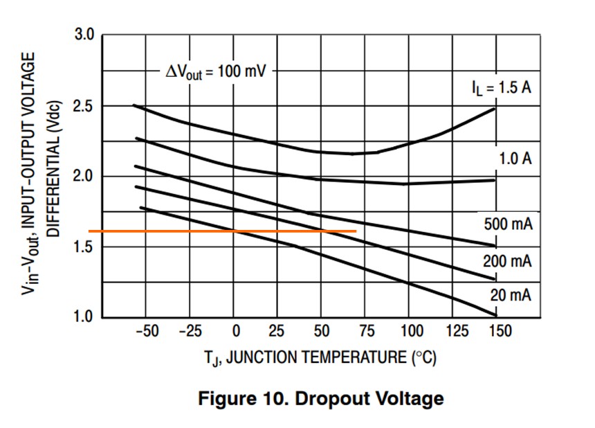
These voltage regulators require a minimum load to maintain stable operation. Resistors R3 and R17 are included in the design to provide this minimum load, ensuring consistent voltage regulation. It’s also important to consider the dropout voltage of the regulators, which is the minimum voltage difference required between the input and output for proper regulation. In this case, the regulators operate close to their dropout voltages. According to datasheets, at a 20mA load and 0℃, the dropout is approximately 1.6V. This allows for a potential increase in op-amp rails up to around 13.4V if needed, offering a safety margin and potential for fine-tuning the system.
For the microcontroller, which is the brain of the ev charger, a stable 5V supply is needed. Due to component availability, a Pro-Mini module, housing an Atmega328P Arduino and a 5V regulator, was chosen. However, it’s critical to note that the onboard regulator of the Pro-Mini has a maximum input voltage limit of 10V. To safely power this module from the regulated 12V rail, a 4.3V Zener diode is used to drop the voltage before it reaches the RAW input of the Pro-Mini. This ensures the microcontroller operates within its safe voltage range.
Pilot Signal Generation: Communicating with the EV
A single wire, referenced to earth, carries the pilot signal, which is the communication lifeline between the ev charger and the electric vehicle. This pilot signal is crucial for initiating, controlling, and monitoring the charging process. Detailed explanations of the pilot signal operation can be found in resources like the OpenEV support articles and the SAE J1772 standard documentation. In essence, the EV communicates its charging state and requirements by changing the resistance on the pilot signal line. These resistance changes translate into voltage variations that the ev charger can interpret.
To generate this crucial pilot signal, an LM358 Op-Amp is used. The Arduino microcontroller outputs a 0-5V PWM (Pulse Width Modulation) signal, which the LM358 op-amp then converts into a +/-12V signal, forming the necessary pilot waveform. This conversion is a fundamental step in enabling communication and control during the ev charging process.
For safety and accurate signal processing, the pilot voltage is conditioned using a voltage divider network before being fed into an Analog-to-Digital Converter (ADC) channel for measurement by the microcontroller. Furthermore, a 13.6V 600W bidirectional TVS (Transient Voltage Suppressor) diode is implemented to protect the circuit from any unexpected voltage surges or transients on the pilot wire, enhancing the robustness and reliability of the ev charger.
Relay Operation: Power Switching and Control
Relays are essential components in an ev charger for safely switching high-power circuits. Initially, the design considered distributing the load across the positive and negative rails of the SMPS (Switched-Mode Power Supply) to potentially balance the load. This would involve powering one relay from the positive rail and the other from the negative rail. However, for the sake of simplicity and reduced component count, both relays were ultimately powered from the positive supply rail. This simplified design proved to be effective and reliable in operation.
The T9VV1K15-12S relays were selected, and their specifications indicate a low coil holding voltage of just 4.7V. This feature is beneficial for power conservation. The circuit design incorporates 100uF capacitors charged from the +15V rail through 1W 47R resistors (R13 & R14). When the relays are activated, they briefly receive 15V for a quick pull-in, but the steady-state voltage then decays to approximately 9V, significantly reducing power consumption during continuous operation. Using larger value resistors, like 68R or even 100R, could further enhance power efficiency by reducing the steady-state current.
BC337 transistors are used to switch the relays. They receive about 2mA of base current through 2.2K resistors, which is sufficient to drive the transistors into saturation and reliably switch the relays. This ensures efficient and controlled switching of the power to the EV during charging.
Current Transformer: Ground Fault Detection for Safety
Safety is paramount in ev charger design, and ground fault detection is a critical safety feature. A current transformer is employed to monitor for ground faults. Analogous to a voltage transformer, a current transformer works on the principle of electromagnetic induction, but for current measurement. In this application, the live and neutral wires are passed once through the ferrite core of the current transformer, creating a single-turn primary winding. The secondary winding consists of hundreds of turns. Any current imbalance between the live and neutral wires, indicating a ground fault, induces a current in the secondary winding, proportional to the turns ratio. For example, a 20mA ground fault current in the primary with a 1:400 turns ratio would induce a 50uA current in the secondary.
It’s crucial to note that, unlike voltage transformers which dislike short circuits, current transformers should not be operated with an open circuit on the secondary side. The preferred method for measuring the secondary current is to use a transimpedance amplifier.
The OP07 low-offset op-amp (U2) is used in a transimpedance amplifier configuration. With the V+ terminal grounded, the op-amp output adjusts to maintain the V- terminal at 0V. If the current transformer pushes 50uA towards the V- terminal, the op-amp reduces its output voltage to -5V, causing the 50uA current to flow entirely through the feedback resistor R2 (100K). This maintains the V- terminal at 0V. Therefore, the current from the transformer is converted into a proportional voltage at the op-amp’s output. Capacitor C1 acts as a low-pass filter, reducing high-frequency noise and gain. Diodes D1 and D2 limit voltage excursions beyond approximately 0.7V, preventing saturation of the transimpedance amplifier.
While the low-offset characteristic of the OP07 might be somewhat redundant due to capacitor C2 removing any DC bias, it was used for robustness. Op-amp U3B is configured as a further amplifier stage and precision rectifier. Zener diodes (4.3V) clip the output to a maximum of approximately 4V. Finally, resistor R12 and capacitor C3 form a low-pass filter before the signal is fed to the Arduino ADC channel for measurement and processing.
In summary, the circuitry effectively converts AC currents from the ground fault current transformer into voltage signals, amplifies, rectifies, limits, and filters them. This processed signal is then sent to the Arduino ADC for ground fault monitoring. While this specific circuit design was implemented and validated, further simplification might be possible in future iterations, highlighting the iterative nature of engineering and design improvement in ev charger technology. This detailed look into the power supply and safety mechanisms underscores the complexity and sophistication within even a seemingly simple device like an ev charger.