For car enthusiasts and DIYers looking to delve into vehicle diagnostics, understanding the OBD2 (On-Board Diagnostics II) system is crucial. This guide walks you through creating a custom Female Obd2 Connector harness, allowing you to interface with your car’s computer for diagnostics and troubleshooting. Please remember, this is a DIY project and should be approached with caution. Incorrect wiring can potentially damage your vehicle’s electronic control unit (ECU). Proceed at your own risk.
Tools and Parts You’ll Need
Before starting, gather these tools and parts:
- Wire strippers/cutters
- Needle-nose pliers
- Molex crimping tool (optional, but recommended for professional results)
- Soldering iron and solder (recommended for a robust connection)
- 4-pin connector (rated for 22-16AWG wire, 1.3-1.7mm insulation/seal size) – Link to Part
- OBD-II Cable (female OBD2 connector end) – Link to Part
If you have spare wire available, you can purchase just the female OBD2 connector and the 4-pin connector separately. Ensure your wire gauge is compatible with the chosen connectors. For this project, we will be focusing on utilizing only four essential wires from the OBD-II connector.
Step-by-Step Guide to Building Your Custom OBD2 Connector
Out of the 16 pins available on a standard female OBD2 connector (OBD2C), we will only utilize four for this DIY harness:
- Pin 4: Chassis Ground (typically orange wire on the OBD2C)
- Pin 6: CAN (J-2234) High (typically green wire on the OBD2C)
- Pin 14: CAN (J-2234) Low (typically brown with white stripe wire on the OBD2C)
- Pin 16: Battery Power (typically green with white stripe wire on the OBD2C)
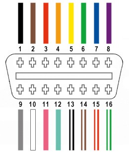 Diagram showing the four OBD2 pins being used
Step 1: Preparing the Wires
It’s often recommended to twist pairs of wires in automotive applications to minimize electromagnetic interference. Begin by carefully removing the outer sheath and shielding from the OBD-II cable to expose the individual wires. Identify and separate the four wires you’ll be using (pins 4, 6, 14, and 16). Bundle the remaining 12 wires aside and secure them with a zip tie to keep them out of your working area.
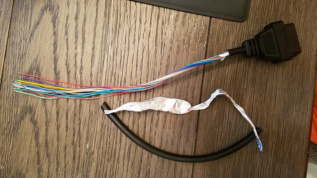 OBD2 cable with sheath and shielding removed, exposing wires
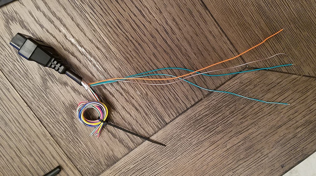 Four essential wires separated from the OBD2 cable
Step 2: Addressing Wire Gauge Compatibility
A common issue arises because the wires in many OBD2 cables are 26AWG, while the pins for the 4-pin connector (4PC) are designed for slightly thicker 22AWG wire. To compensate for this difference, carefully strip approximately 3/8″ of insulation from the end of each of the four selected wires. Fold the exposed wire strands back onto themselves and twist them tightly to effectively thicken the wire gauge, ensuring a better fit within the 4-pin connector pins. Slide a rubber seal (provided with the 4PC kit) onto each wire.
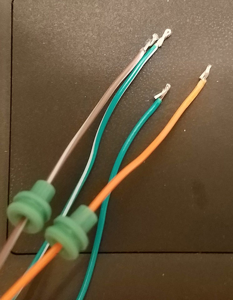 Close-up of a wire folded and twisted to increase thickness for connector pin compatibility
Step 3: Inserting Wires into Connector Pins
The pins for the 4PC have two sets of prongs. The inner set is designed to crimp onto the exposed wire, while the outer set crimps onto the wire seal. Insert the exposed and thickened wire into the pin, aligning it with the inner set of prongs. Due to the small gauge of the wire, using needle-nose pliers to hold the wire in place during the next step is helpful.
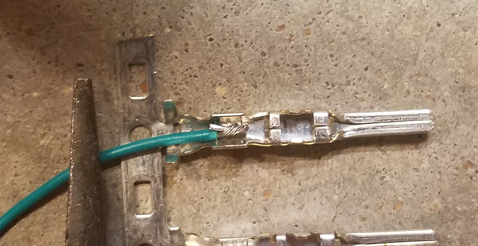 Wire positioned in the connector pin before crimping or soldering
Step 4: Soldering the Wires (Recommended)
Soldering provides a strong and reliable electrical connection. If you choose to solder, apply a small amount of solder to the wire where it meets the pin. This secures the wire in place and ensures good conductivity, especially important given the thin wire gauge.
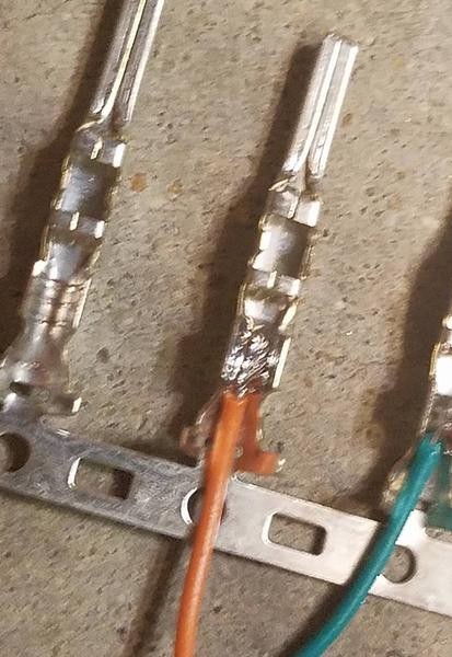 Soldered wire to connector pin, showing solder point
Step 5: Crimping as an Alternative
If you prefer crimping or do not have soldering equipment, use a Molex crimping tool for the best results. If a specialized tool isn’t available, needle-nose pliers can be used carefully. Fold one prong at a time over the wire, ensuring a tight crimp. For added security, you can gently squeeze the prongs further with pliers, but avoid over-crimping, which can damage the pin or wire.
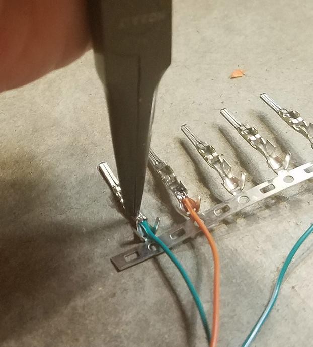 Crimping the prongs of the connector pin over the wire using pliers
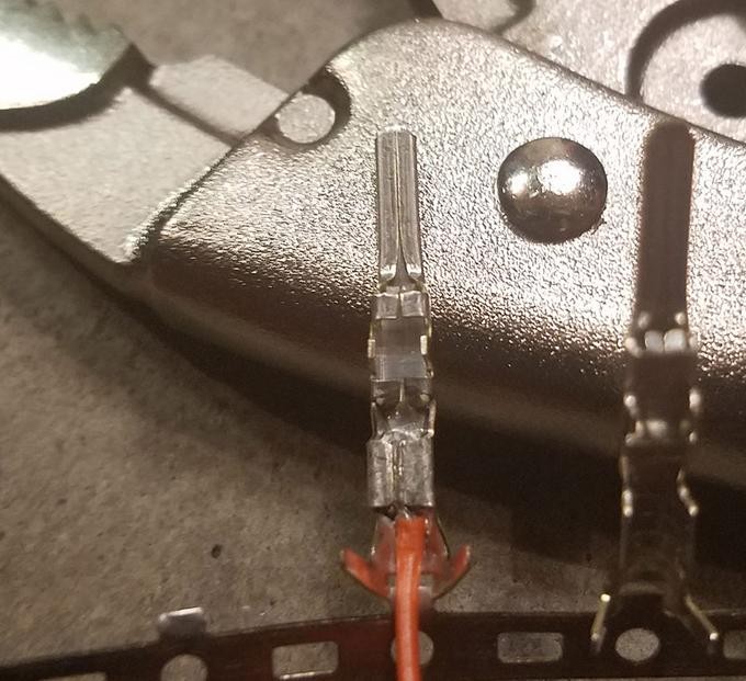 Close-up of crimped connector pin showing prongs folded over the wire
Step 6: Securing the Rubber Seal
Slide the rubber seal up the wire until it sits between the outer set of prongs on the connector pin. Use the same crimping technique (or Molex tool) to fold these outer prongs over the rubber seal. This provides strain relief and environmental protection to the connection.
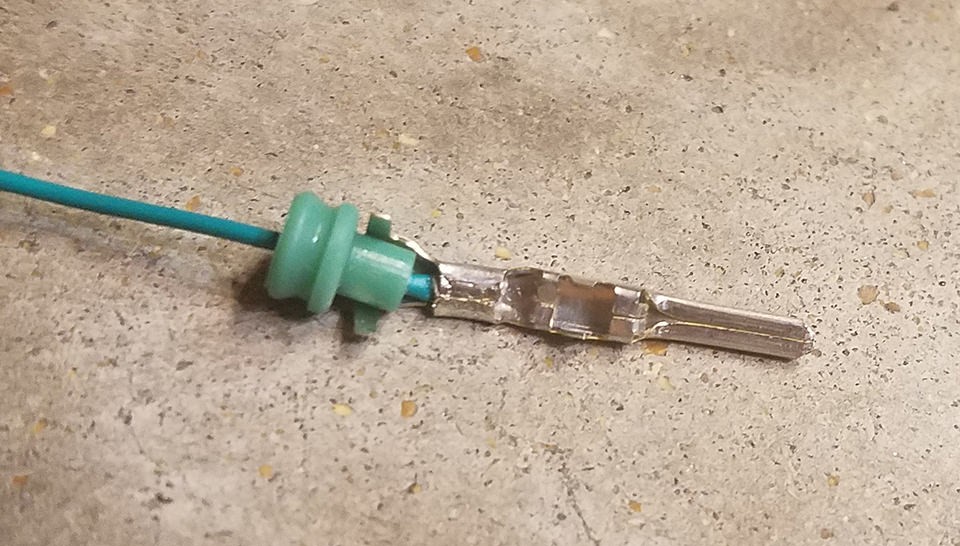 Positioning the rubber seal before crimping the outer prongs
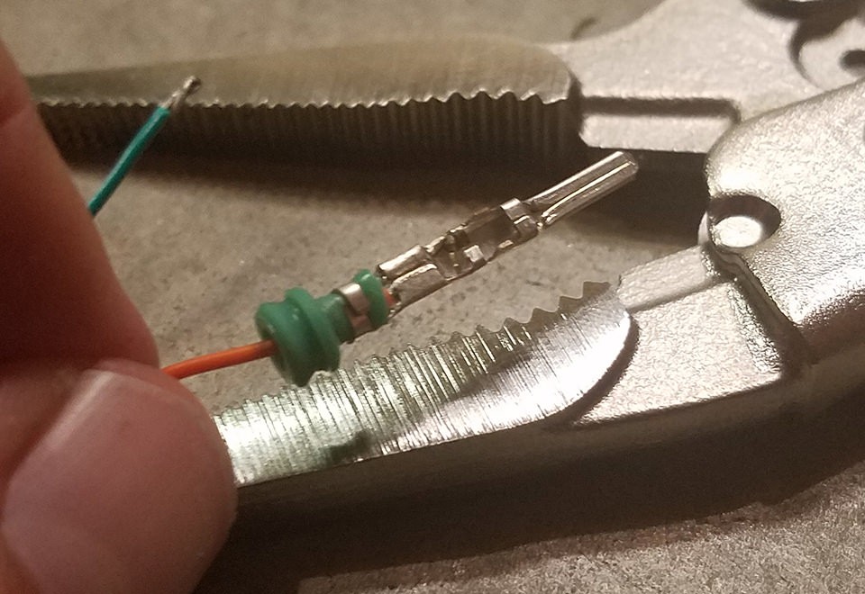 Crimping the outer prongs over the rubber seal for strain relief
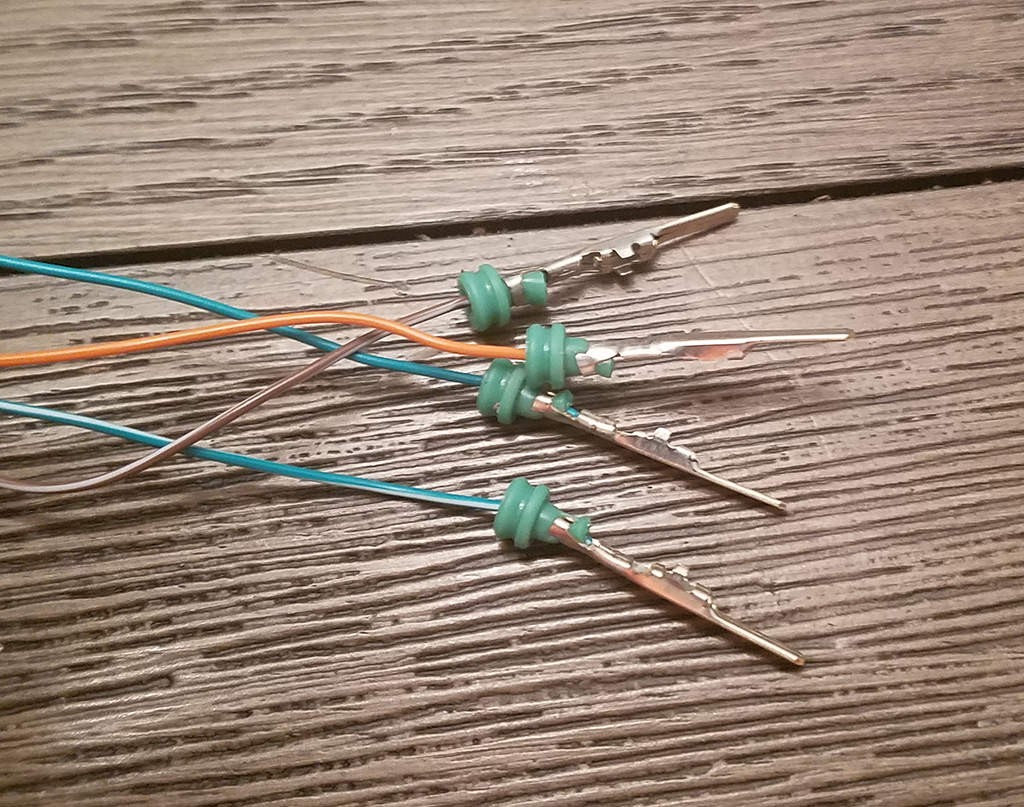 Completed crimped pin with wire and seal secured
Step 7: Wire Pairing and Twisting
Pair and twist the wires as follows:
- Pin 4 (orange) with Pin 16 (green w/white stripe)
- Pin 6 (green) with Pin 14 (brown w/white stripe)
This twisting helps to further reduce potential signal interference.
Step 8: Assembling the 4-Pin Connector
Insert the completed pins into the 4-pin connector housing in the correct orientation:
- Pin 14 (brown w/white stripe) > Connector Slot A
- Pin 6 (green) > Connector Slot B
- Pin 16 (green w/white stripe) > Connector Slot C
- Pin 4 (orange) > Connector Slot D
Push each pin into the rear of the connector until it clicks into place, indicating it is securely locked. Needle-nose pliers can assist in gently pulling the wire from the rear to ensure the pin is fully seated.
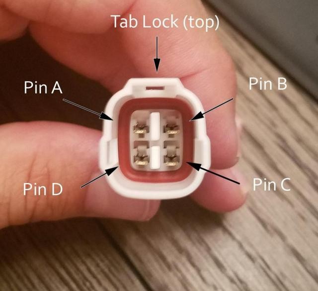 Diagram showing pin insertion order into the 4-pin connector
Testing Your Custom OBD2 Connector
Congratulations! Your custom female OBD2 connector harness is now complete.
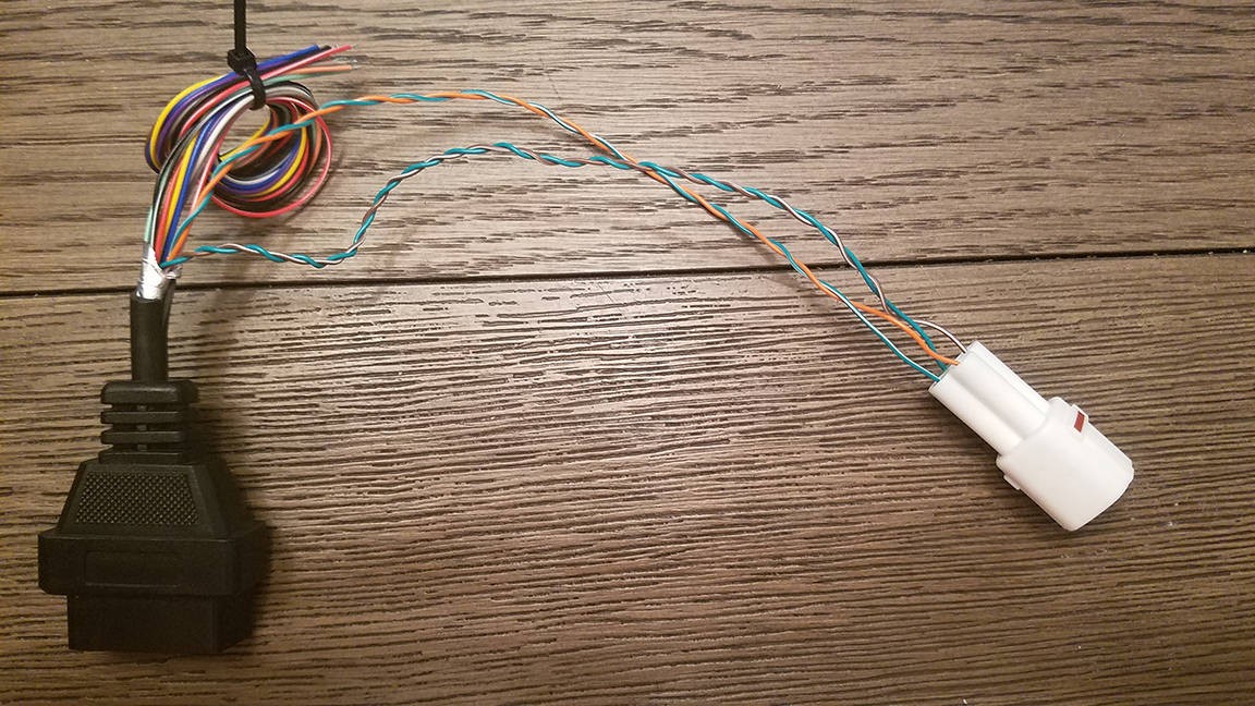 Completed custom OBD2 connector harness
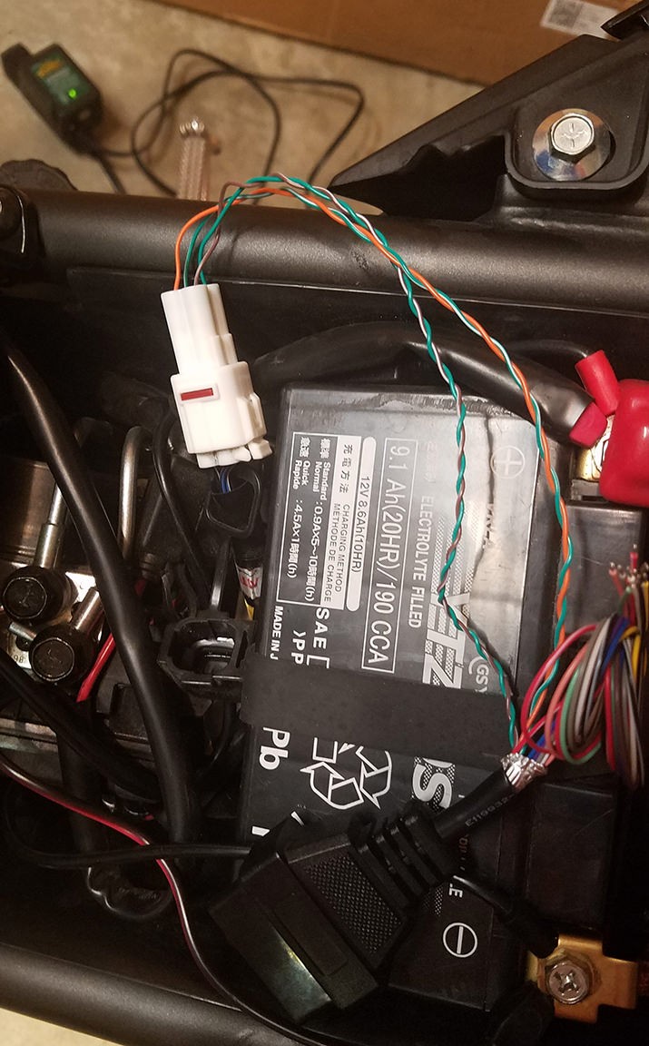 Custom OBD2 connector connected for vehicle diagnostics
You can now test your harness by connecting it to your vehicle’s OBD2 port and using a compatible diagnostic tool to read and clear error codes.
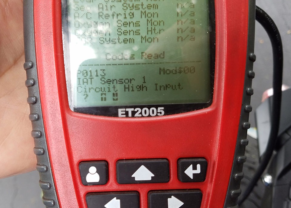 Successfully used custom OBD2 connector to clear a vehicle error code
If any step is unclear, review the instructions and images again. Building this female OBD2 connector can be a rewarding DIY project that enhances your ability to perform vehicle diagnostics.