For automotive enthusiasts and DIY mechanics, having the ability to perform car diagnostics at home can be incredibly useful. An essential tool for this purpose is an OBD2 adapter. While you can purchase pre-made adapters, building your own OBD2 adapter can be a rewarding project, saving you money and providing a deeper understanding of the technology. This guide provides a step-by-step walkthrough to create your own basic OBD2 adapter, enabling you to read diagnostic trouble codes and access vehicle data.
Tools and Parts You’ll Need
Before starting, gather the necessary tools and parts. This DIY project is straightforward and requires only a few common items:
- Wire strippers/cutters
- Needle-nose pliers
- Molex crimping tool (optional, but recommended for a professional finish)
- Soldering iron and solder (recommended for a more secure connection)
For the components, you will need:
- 4-Pin Connector (link to part used; suitable for 22-16AWG wire; insulation/seal size: 1.3-1.7mm)
- OBD-II Cable (link to part used)
If you have spare wires, you can purchase just the female OBD-II connector and use your own wires to connect the OBD-II and 4-pin connectors. Ensure you select the correct 4-pin connector size based on your wire gauge.
Understanding OBD2 Wiring
The OBD-II connector (OBD2C) has 16 pins, but for basic diagnostics, we only need to focus on four essential connections:
- Pin 4: Chassis Ground (typically an orange wire on the OBD2C)
- Pin 6: CAN (J-2234) High (typically a green wire on the OBD2C)
- Pin 14: CAN (J-2234) Low (typically a brown wire with a white stripe on the OBD2C)
- Pin 16: Battery Power (typically a green wire with a white stripe on the OBD2C)
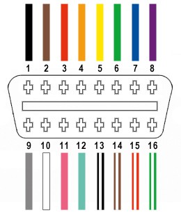 OBD2 Connector Pinout
Step-by-Step Guide to Building Your OBD2 Adapter
Follow these steps to assemble your DIY OBD2 adapter:
Step 1: Prepare the OBD-II Cable Wires
Many guides suggest twisting pairs of wires for better signal integrity. Begin by carefully removing the outer sheath and shielding from the OBD2C cable to expose the individual wires. Identify and separate the four wires you will be using (pins 4, 6, 14, and 16). Secure the remaining 12 wires out of the way using a zip tie to keep your workspace tidy.
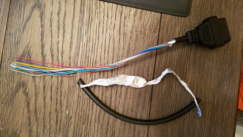 Stripped OBD2 Cable Sheath and Shielding
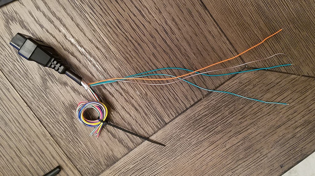 Separated Wires for OBD2 Adapter
Step 2: Prepare the Wire Ends and Seals
The wires in the OBD2C are typically 26AWG, which is thinner than the 22AWG pin size of the 4-pin connector (4PC). To ensure a secure connection, you’ll need to thicken the wire ends. The OBD2C wires come pre-stripped with a short exposed section. Strip off an additional amount to have about 3/8″ of exposed wire. Fold this exposed wire over itself and twist it to increase its thickness, making it a better fit for the 4-pin connector pins. Slide one of the provided rubber seals onto each of the four wires.
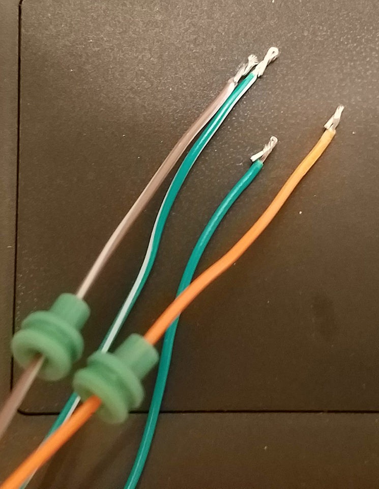 Preparing Wire Ends and Rubber Seals
Step 3: Position the Wire in the Pin Connector
Examine the pins for the 4PC. You’ll notice two sets of prongs. The front prongs are designed to crimp onto the exposed wire, and the rear prongs crimp onto the rubber seal. Insert the exposed wire into the pin connector, aligning it with the front prongs. Due to the small gauge of the wire, using needle-nose pliers to hold the wire in place during the next step can be helpful.
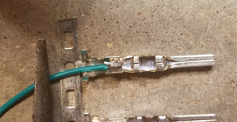 Positioning Wire in Pin Connector
Step 4: Solder the Wire to the Pin Connector (Recommended)
Soldering provides a robust and reliable connection, especially beneficial when working with thin wires. Solder the wire to the pin connector, ensuring a solid bond. If you are new to soldering, numerous online resources, like YouTube tutorials, can provide helpful tips and techniques for successful soldering.
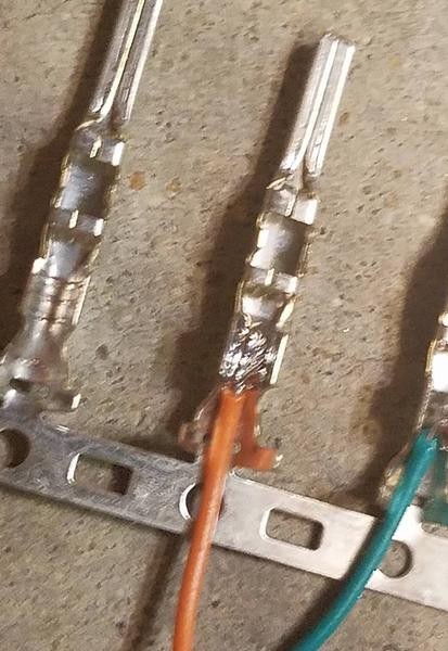 Soldering Wire to Pin Connector
Step 5: Crimp the Connector (Alternative Method)
If you have a Molex crimping tool, use it to crimp the front prongs of the connector securely around the wire. If you don’t have this tool, needle-nose pliers can be used as an alternative. Carefully fold one prong at a time over the wire using the pliers at an angle. You can find video tutorials online demonstrating how to crimp connectors using pliers. For added security, you can gently squeeze the prongs further with pliers to ensure a tight grip, though be careful not to over-crimp and damage the connection.
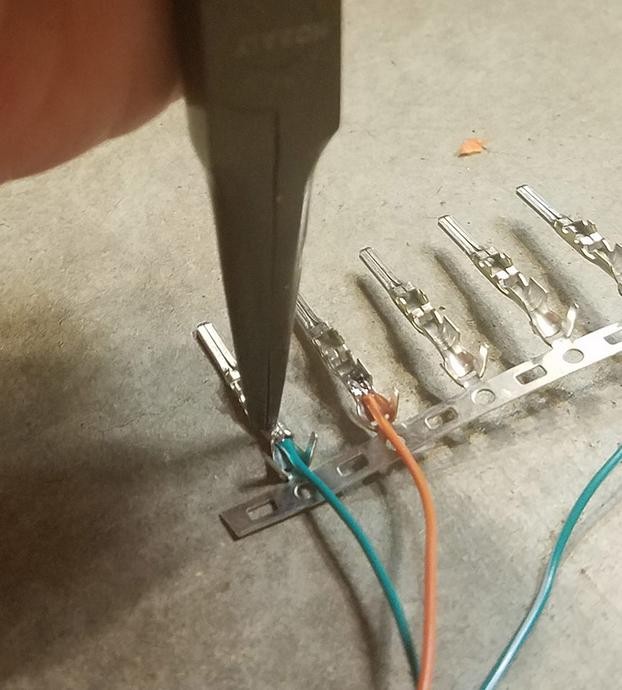 Crimping Connector with Pliers
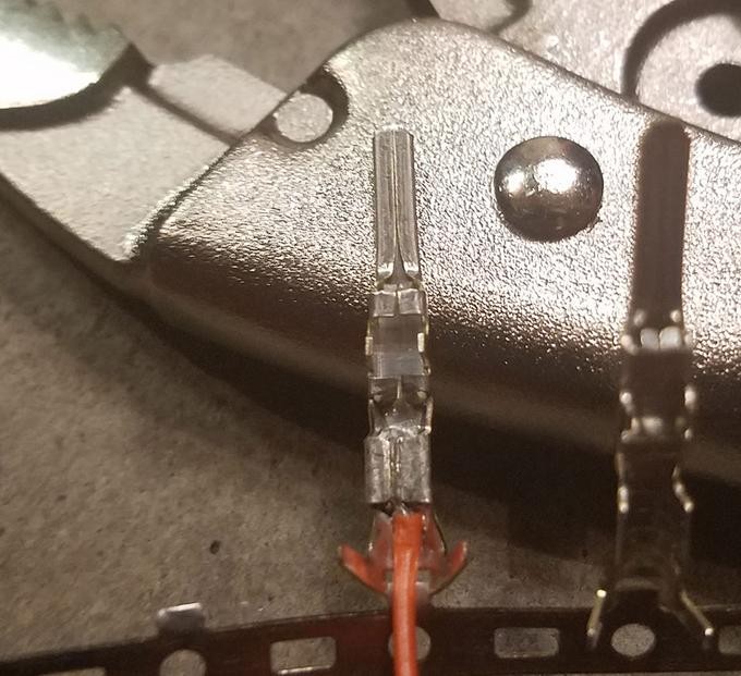 Crimped Pin Connector Detail
Step 6: Crimp the Seal Prongs
Slide the rubber seal up the wire until it sits between the rear prongs of the pin connector. Use the same crimping technique with pliers to fold these prongs over the rubber seal. This secures the seal and provides strain relief for the wire.
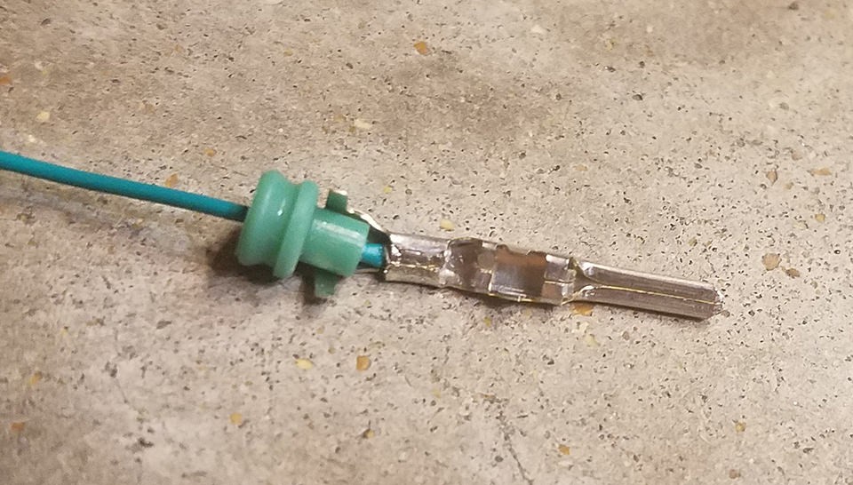 Crimping Seal Prongs – Step 1
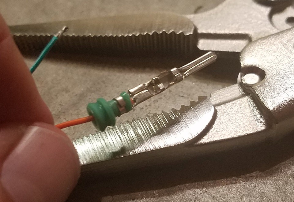 Crimping Seal Prongs – Step 2
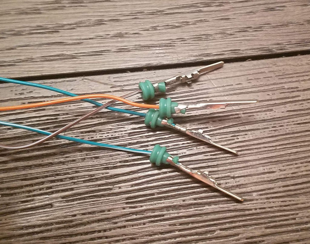 Crimping Seal Prongs – Step 3
Step 7: Twist Wire Pairs
While the exact reason isn’t definitively known, many DIY guides recommend twisting certain wire pairs, possibly to reduce electromagnetic interference. Pair and twist the wires as follows:
- Pin 4 (orange) with Pin 16 (green w/white stripe)
- Pin 6 (green) with Pin 14 (brown w/white stripe)
Step 8: Insert Pins into the 4-Pin Connector Housing
Insert the prepared pins into the 4-pin connector housing (4PC) in the correct orientation as shown below:
- Pin 14 (brown w/white stripe) > Connector Slot A
- Pin 6 (green) > Connector Slot B
- Pin 16 (green w/white stripe) > Connector Slot C
- Pin 4 (orange) > Connector Slot D
Push each pin into the rear of the connector housing until you hear a click, indicating it is locked in place. Using needle-nose pliers to gently pull the wire from the rear can help ensure the pin is fully seated and locked.
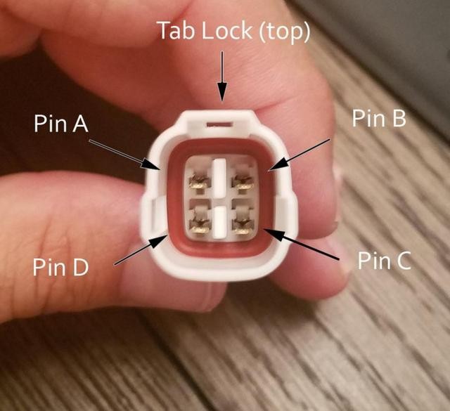 4-Pin Connector Pin Insertion
Conclusion
Congratulations! You have now built your own basic OBD2 adapter!
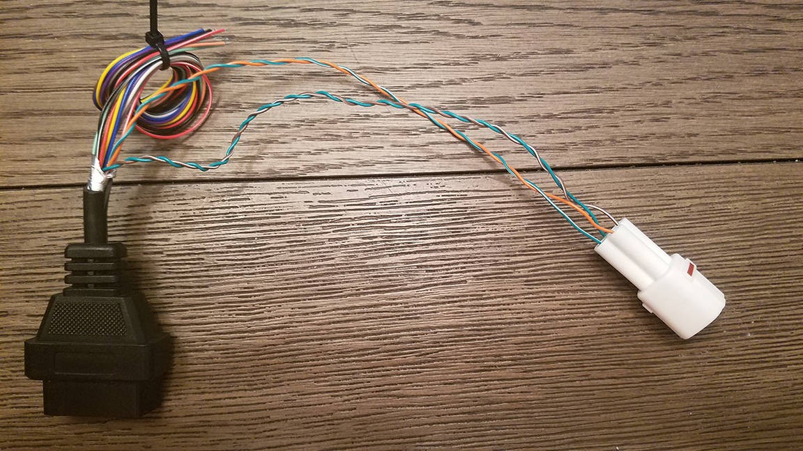 Completed DIY OBD2 Adapter
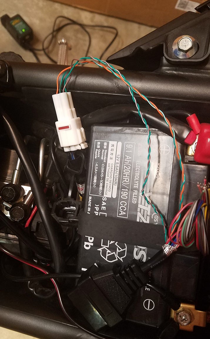 DIY OBD2 Adapter Connectors
This DIY OBD2 adapter can be used with various OBD2 diagnostic tools and software to read and clear diagnostic trouble codes, giving you valuable insights into your vehicle’s health.
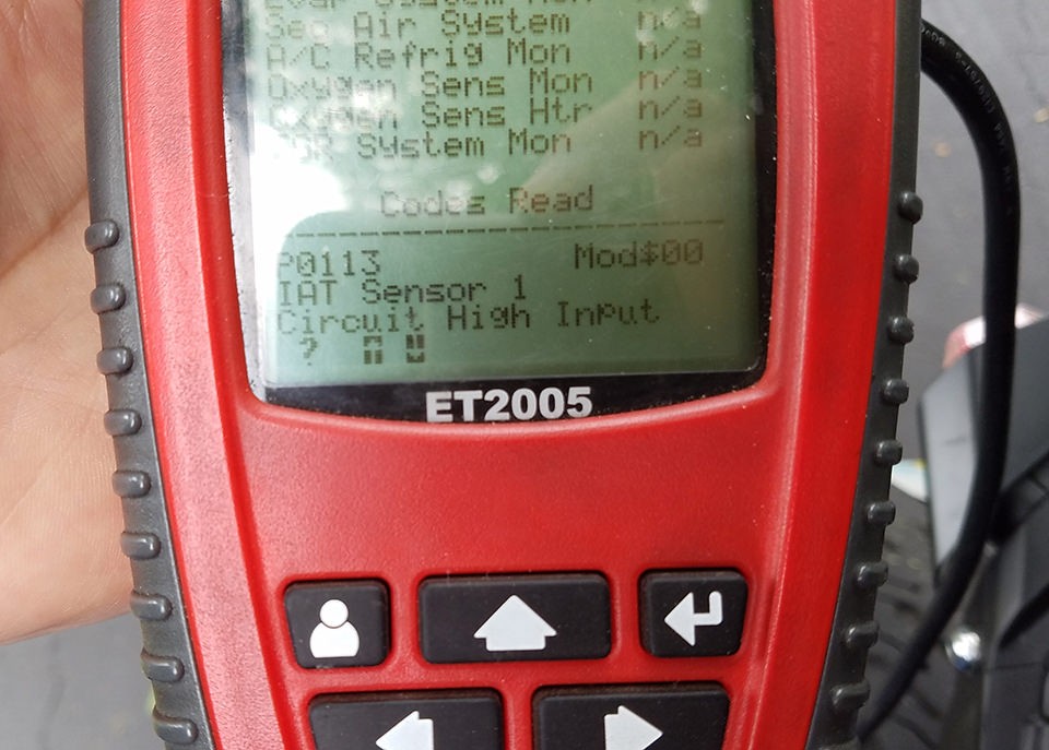 Testing the DIY OBD2 Adapter
Remember, while this guide provides a cost-effective way to create an OBD2 adapter, always exercise caution and double-check your connections. If you encounter any issues or are unsure about any step, consult with experienced professionals or refer to more detailed resources on automotive diagnostics and OBD2 adapter creation. Enjoy using your newly crafted tool for vehicle diagnostics!