Need to understand the Obd2 Connector Pinout for car diagnostics and repair?
This in-depth guide provides a comprehensive overview of the OBD2 connector pinout, also known as the 16-pin Diagnostic Link Connector (DLC). We’ll break down each pin, its function, and its importance in accessing your vehicle’s onboard diagnostic system.
Whether you’re a seasoned mechanic or a DIY enthusiast, understanding the OBD2 connector pinout is crucial for effective vehicle diagnostics, data logging, and troubleshooting. Let’s dive into the details of this essential interface.
In this article
Understanding the OBD2 Connector Pinout: The Key to Vehicle Diagnostics
The On-Board Diagnostics II (OBD2) system is a standardized protocol that allows you to access vital information from your vehicle’s computer. The gateway to this system is the OBD2 connector, a 16-pin interface typically located within easy reach inside your car’s cabin.
When you see the “check engine light” illuminate on your dashboard, it’s a signal that your car’s self-diagnostic system has detected an issue. To decipher these signals, mechanics and car enthusiasts alike use OBD2 scanners. These tools connect to your vehicle through the OBD2 connector, sending requests and receiving responses containing diagnostic trouble codes (DTCs), real-time sensor data, and much more. This capability significantly streamlines the process of identifying and resolving vehicle problems.
Understanding the OBD2 system and connector is crucial for modern vehicle diagnostics, allowing users to read error codes and monitor vehicle health.
Is My Car Equipped with an OBD2 Connector?
The good news is that if you own a relatively recent non-electric vehicle, it almost certainly supports OBD2. While a 16-pin connector is a strong indicator, it’s not foolproof for older models. Some vehicles might feature the connector without fully complying with the OBD2 standard.
Here’s a general guideline based on the region where your car was initially purchased:
 Does My Car Have OBD2?
This chart provides a quick reference to determine OBD2 compliance based on the vehicle’s region and year of manufacture, helping users identify if their car supports the standard.
A Brief History of OBD2 and the Connector Standardization
The OBD2 standard has its roots in California, driven by the California Air Resources Board (CARB)’s mandate for emission control diagnostics in new vehicles starting from 1991.
The Society of Automotive Engineers (SAE) played a crucial role in standardizing OBD2, including the Diagnostic Trouble Codes (DTCs) and, importantly, the OBD connector itself through the SAE J1962 standard. This standardization ensured compatibility across different vehicle manufacturers.
The rollout of OBD2 was gradual but comprehensive:
- 1996: OBD2 became mandatory in the USA for cars and light trucks.
- 2001: The European Union mandated OBD2 for gasoline vehicles.
- 2003: OBD2 (known as EOBD in Europe) became compulsory for diesel vehicles in the EU.
- 2005: OBD2 was extended to medium-duty vehicles in the US.
- 2008: US regulations required vehicles to use ISO 15765-4 (CAN) as the foundation for OBD2 communication.
- 2010: OBD2 compliance was extended to heavy-duty vehicles in the US.
The historical timeline of OBD2 development showcases its evolution from emission control origins to becoming a standard for comprehensive vehicle diagnostics.
A visual timeline highlighting key milestones in OBD2 history, emphasizing its progressive adoption across different vehicle types and regions.
An outlook on the future of OBD, hinting at OBD3 and the potential for remote diagnostics and integration with cloud and IoT technologies.
The Future of OBD2: Trends and Challenges
While OBD2 remains a cornerstone of vehicle diagnostics, the automotive landscape is evolving.
One significant trend is the rise of electric vehicles (EVs). Interestingly, EVs are not obligated to support OBD2 in the traditional sense. Many modern EVs are moving away from standard OBD2 requests, opting instead for OEM-specific UDS communication. This shift can pose challenges for accessing diagnostic data from EVs unless decoding methods are reverse-engineered.
Another development is the emergence of enhanced OBD protocols like WWH-OBD (World Wide Harmonized OBD) and OBDonUDS (OBD on UDS). These protocols aim to modernize OBD communication by utilizing the UDS protocol as a base, offering potential improvements in data richness and communication efficiency.
Looking further ahead, the concept of OBD3 envisions integrating telematics into vehicles. This could involve incorporating a radio transponder in cars to wirelessly transmit Vehicle Identification Numbers (VINs) and DTCs to a central server for automated emissions testing and diagnostics. While offering convenience and cost savings, OBD3 raises privacy concerns related to data surveillance.
Furthermore, the increasing use of OBD2 for third-party data access is facing pushback from some automotive manufacturers. Concerns about data security and the desire to control automotive data are leading to proposals to limit OBD2 functionality during normal driving, potentially impacting the market for aftermarket OBD2 services and devices.
The increasing prevalence of electric vehicles and potential changes in data access methods represent a significant shift in the future of OBD and vehicle diagnostics.
Explore the ‘Ultimate CAN Guide’
Want to deepen your understanding of CAN bus technology?
Our comprehensive 160+ page PDF guide offers 12 ‘simple intros’ to CAN bus and related topics:
Download now
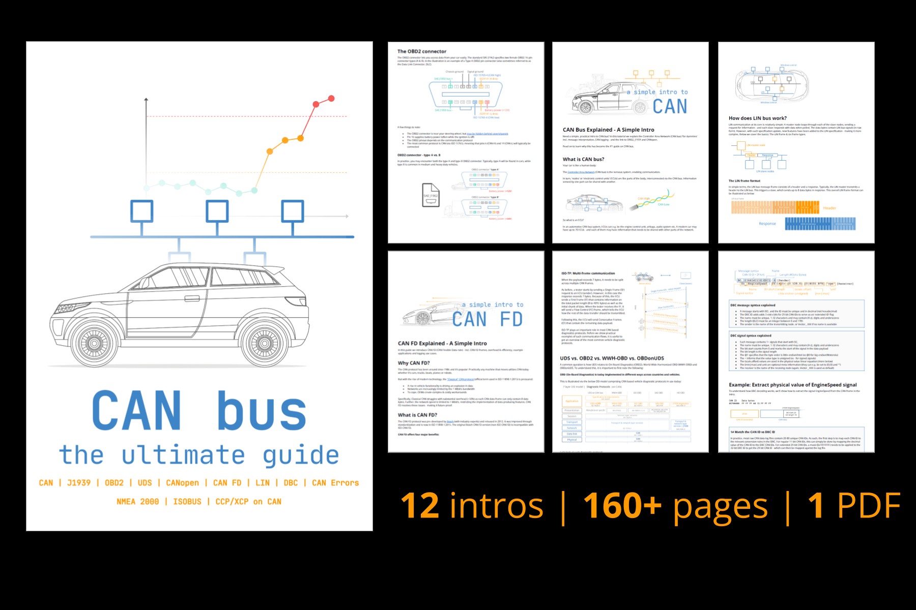 CAN Bus – The Ultimate Guide Tutorial PDF
OBD2 Standards and the Connector Pinout [SAE J1962 / ISO 15031-3]
OBD2 operates as a higher-layer protocol on top of communication networks like CAN bus. It’s similar to other CAN-based protocols such as J1939, CANopen, and NMEA 2000.
The OBD2 standards encompass various aspects, including the OBD2 connector pinout, lower-layer protocols, and OBD2 Parameter IDs (PIDs).
These standards can be organized using the 7-layer OSI model. Notably, both SAE and ISO standards contribute to different layers, reflecting the US (SAE) and European (ISO) influences on OBD standardization. Many of these standards are technically very similar, such as SAE J1979 and ISO 15031-5, and SAE J1962 and ISO 15031-3.
An OSI model diagram illustrating the relationship between OBD2 and CAN bus standards, highlighting the layered communication architecture.
Now, let’s focus on the OBD2 connector pinout itself, as defined in SAE J1962 / ISO 15031-3. This standard specifies the physical interface that enables communication with your vehicle’s diagnostic system.
A detailed OBD2 connector pinout diagram, showcasing the pin assignments for a Type A female socket, essential for understanding the physical interface.
Decoding the OBD2 Connector Pinout: Pin Functions Explained
The 16-pin OBD2 connector, often called the Data Link Connector (DLC), is designed for easy access to your car’s data. It’s typically located near the steering wheel, though its exact position can vary and may sometimes be hidden behind a panel.
Here’s a breakdown of the functions of each pin in a standard Type A OBD2 connector pinout:
| Pin | Name | Function | Protocol (Typical) |
|---|---|---|---|
| 1 | Manufacturer Discretion | Typically not used, or manufacturer specific | – |
| 2 | SAE J1850 Bus+ | SAE J1850 VPW and PWM bus positive line | SAE J1850 VPW/PWM |
| 3 | Manufacturer Discretion | Typically not used, or manufacturer specific | – |
| 4 | Chassis Ground | Ground for the chassis | – |
| 5 | Signal Ground | Signal ground for the modules | – |
| 6 | CAN High (CAN-H) | CAN bus high signal line | CAN (ISO 15765-4) |
| 7 | ISO 9141-2 K-Line | K-line for ISO 9141-2 and ISO 14230 (KWP2000) | ISO 9141-2/KWP2000 |
| 8 | Manufacturer Discretion | Typically not used, or manufacturer specific | – |
| 9 | Manufacturer Discretion | Typically not used, or manufacturer specific | – |
| 10 | SAE J1850 Bus- | SAE J1850 VPW and PWM bus negative line | SAE J1850 VPW/PWM |
| 11 | Manufacturer Discretion | Typically not used, or manufacturer specific | – |
| 12 | Manufacturer Discretion | Typically not used, or manufacturer specific | – |
| 13 | Manufacturer Discretion | Typically not used, or manufacturer specific | – |
| 14 | CAN Low (CAN-L) | CAN bus low signal line | CAN (ISO 15765-4) |
| 15 | ISO 9141-2 L-Line | L-line for ISO 9141-2 and ISO 14230 (KWP2000) | ISO 9141-2/KWP2000 |
| 16 | Battery Power | +12V battery power supply | – |
Key points about the OBD2 connector pinout:
- Pin 16 provides battery power, even when the ignition is off, which is essential for powering OBD2 scanners and devices.
- Pins 4 and 5 are ground connections, ensuring a stable electrical reference.
- Pins 6 and 14 are dedicated to CAN bus communication, the most prevalent protocol in modern vehicles.
- Pins 2, 7, 10, and 15 are associated with older protocols like SAE J1850 and ISO 9141-2, which may be present in older vehicles.
- The remaining pins (1, 3, 8, 9, 11, 12, 13) are typically manufacturer discretionary, meaning their functions can vary between car brands or even models.
Understanding this pinout is crucial for correctly connecting diagnostic tools, interpreting wiring diagrams, and even for DIY automotive electronics projects.
OBD2 Connector Types: Type A vs. Type B Pinout Variations
While the standard OBD2 pinout is generally consistent, you might encounter two main connector types: Type A and Type B. Type A is the standard in most passenger cars and light-duty vehicles, while Type B is more common in medium and heavy-duty vehicles.
The primary differences between Type A and Type B OBD2 connector pinouts are:
- Power Supply Voltage: Type A typically provides 12V power, while Type B provides 24V, reflecting the different electrical systems in cars versus larger vehicles.
- Physical Keying: Type B connectors feature an interrupted groove in the middle. This physical difference ensures that Type A adapters cannot be accidentally plugged into Type B sockets. However, Type B adapters are often designed to be backward compatible with Type A sockets.
Despite these differences, the core signal pins related to communication protocols (CAN, ISO, J1850) remain largely consistent across both Type A and Type B OBD2 connector pinouts.
A comparison diagram highlighting the key differences between OBD2 Type A and Type B connectors, particularly noting the voltage and physical variations.
A visual representation of the relationship between OBD2 and CAN bus, emphasizing ISO 15765 as the standard for CAN-based OBD2 communication.
OBD2 and CAN Bus: Pinout and Protocol Integration [ISO 15765-4]
Since 2008, CAN bus has become the mandatory lower-layer protocol for OBD2 in US vehicles, as per ISO 15765. This standard, also known as Diagnostics over CAN (DoCAN), outlines specific requirements for using CAN bus in OBD2 systems.
ISO 15765-4 standardizes the CAN interface for diagnostic equipment, focusing on the physical, data link, and network layers. Key specifications include:
- CAN bus bit-rate: Must be either 250K or 500K.
- CAN IDs: Supports both 11-bit and 29-bit CAN identifiers.
- Specific CAN IDs for OBD2 requests and responses.
- Diagnostic CAN frame data length: Limited to 8 bytes.
- OBD2 adapter cable length: Maximum 5 meters.
In the context of the OBD2 connector pinout, pins 6 (CAN-H) and 14 (CAN-L) are the crucial connections for CAN bus communication. In most modern cars, these pins are active and carry the CAN signals used for OBD2 diagnostics.
OBD2 CAN Identifiers and Communication Flow
OBD2 communication over CAN bus relies on a request-response message exchange. Typically, 11-bit CAN IDs are used in passenger cars.
- Functional Addressing Request ID: 0x7DF – Used to broadcast a request to all OBD2-compliant ECUs.
- Physical Addressing Request IDs: 0x7E0-0x7E7 – Used to send requests to specific ECUs (less common).
- Response IDs: 0x7E8-0x7EF – ECUs respond using these IDs. The Engine Control Module (ECM) commonly responds with 0x7E8, and the Transmission Control Module (TCM) with 0x7E9.
In some vehicles, especially larger ones, 29-bit CAN identifiers might be used for OBD2 communication. In this case, the Functional Addressing CAN ID is 0x18DB33F1, and response IDs range from 0x18DAF100 to 0x18DAF1FF.
A visual representation of OBD2 request and response frames, illustrating the flow of data and the role of PIDs in parameter identification.
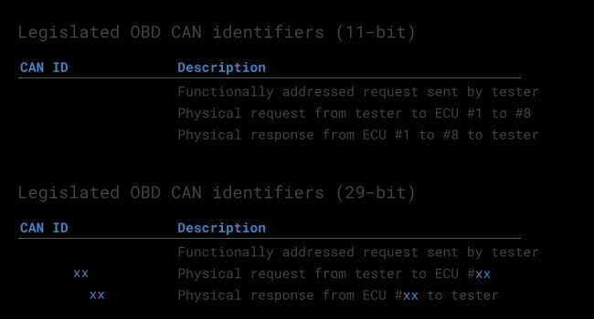 OBD2 OBD CAN bus Identifiers 7DF 7E8 7E0
A conceptual diagram contrasting OBD2 CAN bus communication with OEM-specific proprietary CAN protocols, highlighting the difference in data accessibility.
OBD2 vs. Proprietary CAN Protocols: Understanding the Difference
It’s important to recognize that OBD2 is an additional protocol layer on top of a vehicle’s internal communication network. Car manufacturers implement their own proprietary CAN protocols for the core functions of the vehicle’s Electronic Control Units (ECUs). These proprietary protocols are often specific to the vehicle brand, model, and year, and are generally not publicly documented.
When you connect an OBD2 scanner or data logger to your car’s OBD2 connector pinout, you are primarily accessing the OBD2 protocol data. While you might also observe some OEM-specific CAN data on the same connector, interpreting this proprietary data typically requires reverse engineering.
Think of OBD2 as a standardized ‘diagnostic language’ that sits alongside the OEM’s ‘internal language’ for vehicle control. The OBD2 connector pinout provides access to both, but understanding and utilizing them requires different approaches.
Determining Bit-rate and CAN ID Type
Since OBD2 over CAN can use either 250K or 500K bit-rates and 11-bit or 29-bit CAN IDs, it’s essential to determine the correct combination for a specific vehicle. ISO 15765-4 provides a recommended initialization sequence to automatically detect the appropriate settings. This process involves sending specific OBD2 requests and checking for valid responses.
A flowchart illustrating the process of OBD2 bit-rate and CAN ID validation, guiding users through the steps to correctly configure communication parameters.
A diagram showcasing the five primary lower-layer protocols used in OBD2, including CAN (ISO 15765), KWP2000, SAE J1850, and ISO 9141, highlighting protocol diversity.
Legacy OBD2 Protocols and Pinout Considerations
While CAN bus is dominant today, older vehicles might utilize different lower-layer protocols for OBD2. It’s helpful to be aware of these legacy protocols and their potential pin assignments within the OBD2 connector pinout:
- ISO 15765 (CAN bus): Pins 6 and 14 (as discussed).
- ISO 14230-4 (KWP2000): Typically uses pin 7 (K-line) and optionally pin 15 (L-line).
- ISO 9141-2: Uses pin 7 (K-line) and pin 15 (L-line).
- SAE J1850 VPW: Pin 2 (Bus+) and pin 10 (Bus-).
- SAE J1850 PWM: Pin 2 (Bus+) and pin 10 (Bus-).
Understanding these protocol-specific pin assignments can be useful when diagnosing older vehicles or working with pre-CAN OBD2 systems.
OBD2 Data Logging and Decoding: Practical Applications
Understanding the OBD2 connector pinout and protocols opens up possibilities for practical applications like data logging and vehicle diagnostics. Tools like the CANedge CAN bus data logger can be connected to the OBD2 connector via an adapter cable to record and analyze vehicle data.
A diagram illustrating the use of an OBD2 data logger to capture PID data, showcasing the request-response mechanism and data flow.
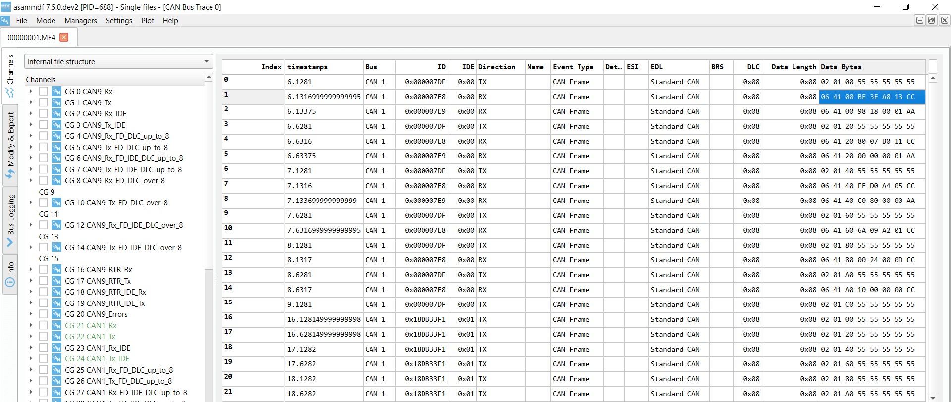 OBD2 Supported PIDs Test Screenshot of an OBD2 Supported PIDs test response within asammdf software, showing the tool’s capability to interpret and display diagnostic data.
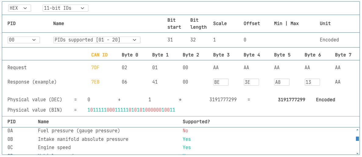 Review supported PIDs via OBD2 lookup tool
Steps for OBD2 Data Logging and Decoding:
- Test Bit-rate, IDs, and Supported PIDs: Use diagnostic tools to automatically detect the correct bit-rate and CAN ID type for your vehicle. Send ‘Supported PIDs’ requests to identify which parameters your vehicle supports.
- Configure OBD2 PID Requests: Set up your data logger to transmit requests for the specific PIDs you want to monitor. Consider using ‘Physical Addressing’ to target specific ECUs and optimize data acquisition.
- DBC Decode Raw OBD2 Data: Utilize a DBC (CAN database) file designed for OBD2 to decode the raw CAN data into human-readable physical values. This simplifies data analysis and visualization.
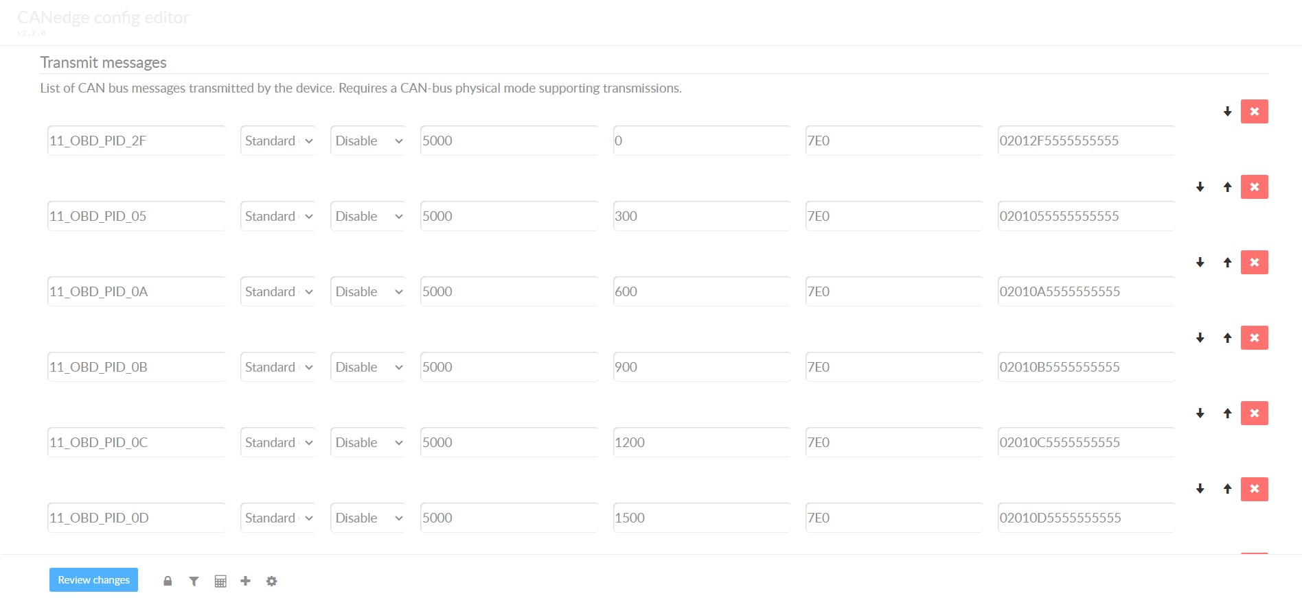 obd2-transmit-list-example-canedge Example configuration of an OBD2 transmit list within CANedge, demonstrating how users can specify PIDs for data logging.
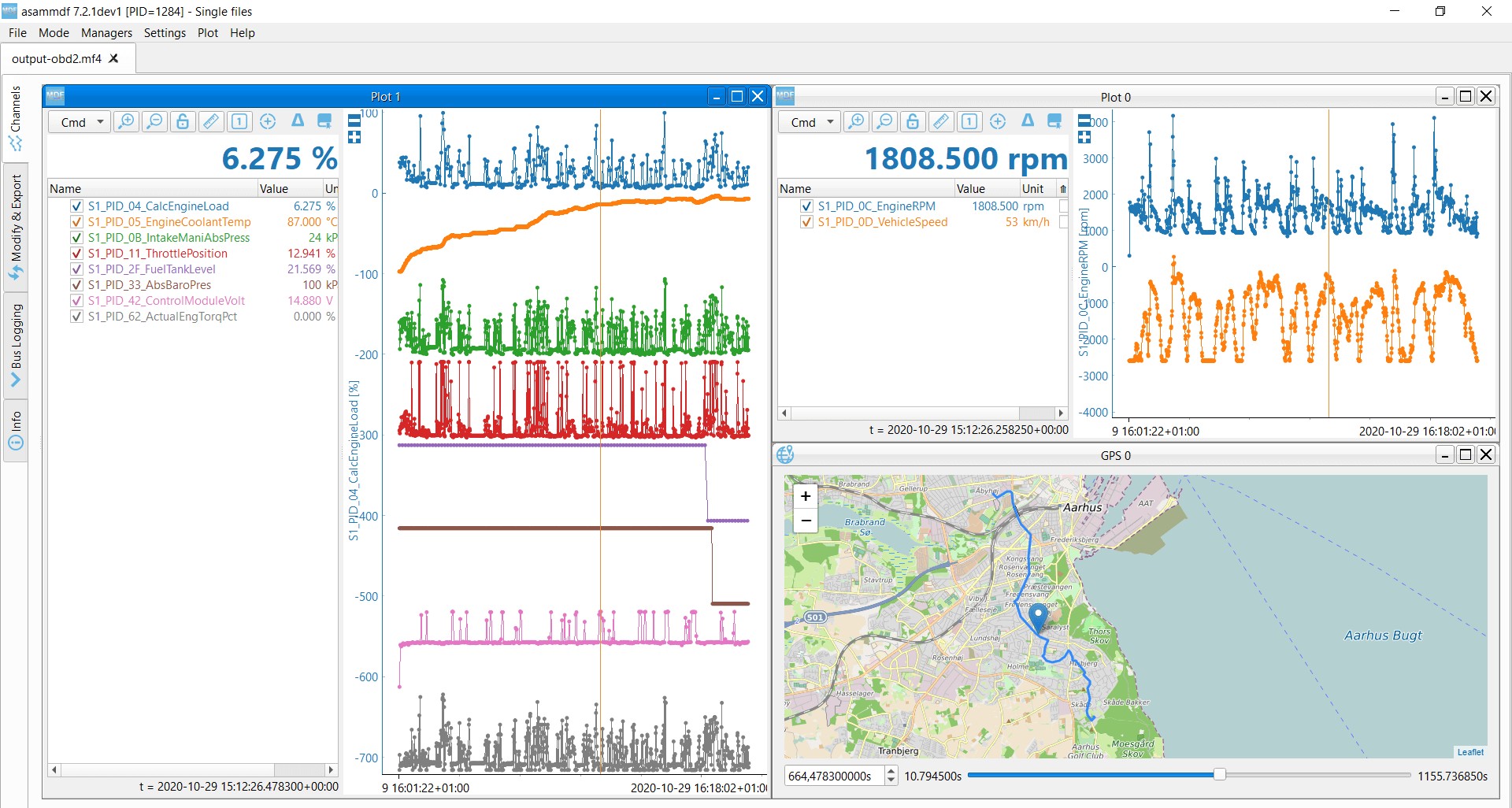 OBD2 data decoded visual plot asammdf CAN bus DBC file Visualization of decoded OBD2 data in asammdf software, showcasing plots of vehicle parameters derived from logged data.
Understanding the OBD2 connector pinout is the first step towards unlocking a wealth of vehicle data for diagnostics, performance analysis, and custom automotive projects. By combining this knowledge with appropriate tools and techniques, you can gain valuable insights into your vehicle’s operation and health.
Conclusion: The OBD2 Connector Pinout – Your Gateway to Vehicle Data
The OBD2 connector pinout is more than just a physical interface; it’s the key to accessing your vehicle’s onboard diagnostic system and a wealth of valuable data. Understanding the function of each pin, the different connector types, and their relationship to communication protocols like CAN bus is essential for anyone working with modern vehicle diagnostics and data acquisition.
Whether you’re a professional mechanic, a car enthusiast, or an engineer, mastering the OBD2 connector pinout empowers you to effectively diagnose issues, log vehicle parameters, and explore the intricacies of automotive communication networks. As vehicle technology continues to evolve, a solid understanding of the OBD2 connector and its pinout will remain a fundamental skill in the automotive field.
Need to log or stream OBD2 data?
Explore our OBD2 data logging solutions today!
Buy now Contact us
Recommended for you
OBD2 DATA LOGGER: EASILY LOG & CONVERT OBD2 DATA
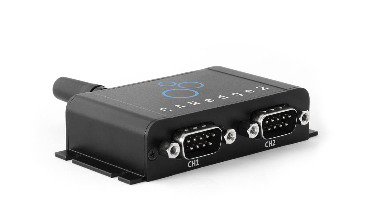 CANedge2 – Dual CAN Bus Telematics Dongle CANEDGE2 – PRO CAN IoT LOGGER
[