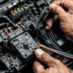
As a mechanical engineer venturing into automotive electronics, understanding how to synchronize a DC motor with your engine’s RPM is a fascinating challenge. You’re aiming for a 100% RPM match, regardless of engine load, and you’re exploring various methods to achieve this. Let’s break down your approach and see how an Obd2 Throttle Controller fits into this picture, and if it’s the right tool for your ambitious project.
You’re considering using a tachometer with RS232 or CAN output, or even the crankshaft sensor’s voltage to read engine RPM. These are all valid starting points. Tapping into the engine’s RPM signal is crucial for any synchronization strategy. Your initial thought of using a tachometer with digital outputs like RS232 or CAN is logical for directly feeding data into a control system. Crankshaft sensor output is another direct engine speed signal, although it might require signal conditioning.
However, you’ve raised a critical point: load and torque. You mentioned concerns about whether you should be focusing on engine load/torque instead of just RPM. It’s true that engine RPM alone doesn’t tell the whole story. Engine load, which directly relates to torque, is equally important in understanding the engine’s operating condition. A Curtis 1244 DC Motor Controller, as you mentioned, is designed to manage both RPM and load/torque of the motor it controls. The question then becomes, how do you instruct this motor controller based on the engine’s load?
This is where things get interesting in relation to an OBD2 throttle controller. A standard OBD2 throttle controller primarily modifies the signal to your electronic throttle body. It intercepts and alters the accelerator pedal position sensor signal before it reaches the engine control unit (ECU). This modification changes how quickly the throttle opens or closes for a given pedal input, effectively adjusting throttle response. While some advanced OBD2 devices might offer the capability to read engine parameters via the OBD2 port, their core function is not to control external devices like DC motors based on engine load or RPM.
Thinking about your target and approach, let’s refine the strategy. Directly using an OBD2 throttle controller to synchronize a DC motor to engine RPM isn’t a direct application. Throttle controllers are designed to adjust throttle response for driver feel, not for precise motor synchronization. They don’t typically output the kind of control signals needed for a DC motor controller.
Your approach of detecting engine RPM via a tachometer and then converting that signal to CAN for the DC motor controller is on the right track. However, let’s consider a more streamlined and potentially more effective approach if we aim for engine RPM synchronization, possibly considering engine load indirectly.
If I were in your position, aiming for 100% real-time RPM synchronization, my approach would be slightly different and might bypass the direct use of an OBD2 throttle controller in the control loop, focusing on its diagnostic potential instead:
-
Direct Engine RPM Sensing: Stick with your idea of using a tachometer or crankshaft sensor. These provide the most direct and immediate feedback of engine RPM. A crankshaft sensor, being integral to the engine’s operation, is often a robust and reliable source.
-
Signal Processing and Control Unit: Instead of an RS232 to CAN converter as an intermediary (which could introduce delay), consider a microcontroller-based system. A microcontroller (like an Arduino or a more industrial-grade option) can directly read the tachometer or crankshaft sensor signal. It can process this signal and generate the appropriate control signal for your Curtis 1244 DC Motor Controller. Microcontrollers offer real-time processing capabilities crucial for minimizing delay in your synchronization.
-
Load Consideration (Indirect): While directly measuring engine load can be complex, you can infer load changes from RPM fluctuations under varying throttle positions and potentially from manifold absolute pressure (MAP) sensor readings. If you can access MAP sensor data (which is available via the OBD2 port), you could incorporate this into your microcontroller’s control algorithm to refine the motor’s response. This is where the OBD2 system becomes valuable – not as a direct controller, but as a source of supplementary data. You could use an OBD2 reader connected to your microcontroller to get MAP or throttle position sensor data to enhance your control strategy. This data, combined with RPM from the tachometer/crankshaft sensor, gives a more complete picture of the engine’s state.
-
DC Motor Controller Interface: Ensure your microcontroller can output the correct control signal format for the Curtis 1244. This might be a PWM signal, analog voltage, or a CAN bus command, depending on the specific Curtis 1244 model and its control inputs.
-
OBD2 for Diagnostics and Monitoring (Optional): While not for direct control in this scenario, an OBD2 throttle controller interface or an OBD2 scanner can be incredibly useful for monitoring engine parameters. You can use an OBD2 reader (separate from a throttle controller device) to log engine RPM, MAP, throttle position, and other relevant data to fine-tune your synchronization algorithm. This data can help you understand how engine load affects RPM and optimize your motor control for various operating conditions.
In essence, while an OBD2 throttle controller in its typical form isn’t the direct solution for synchronizing a DC motor to engine RPM, the OBD2 system itself—and the data it provides—can be a valuable resource. Focus on direct RPM sensing using tachometer or crankshaft sensor, utilize a microcontroller for real-time control, and consider incorporating OBD2 data (like MAP or throttle position) for a more sophisticated and load-aware synchronization. This approach should give you the precise and responsive engine RPM tracking you’re aiming for, surpassing the limitations of solely relying on a throttle controller for this specific task.
