Are you looking to perform your own car diagnostics but finding yourself needing a specific adapter cable? Perhaps you’re working with a system that requires a custom connection, or maybe you just enjoy the satisfaction of DIY projects. Whatever your reason, creating your own Obd2 Adapter Cable can be a rewarding and cost-effective solution. This guide will walk you through the process of building a simple OBD2 adapter cable, focusing on connecting to the essential CAN bus system used in many modern vehicles.
This project focuses on creating a basic OBD2 adapter cable for specific diagnostic purposes, and while it’s a useful skill to learn, remember this is a DIY approach. It’s crucial to proceed with caution and understand that you are undertaking this project at your own risk. We’re sharing this guide based on successful personal experience, but we cannot be responsible for any unintended consequences. Ensure you double-check all connections and understand your vehicle’s diagnostic system before proceeding.
What is an OBD2 Adapter Cable and Why DIY?
OBD2, or On-Board Diagnostics II, is a standardized system used in most modern vehicles to monitor and report on various vehicle parameters. The OBD2 port, typically located within the driver’s cabin, allows access to this data using diagnostic tools. An OBD2 adapter cable acts as an intermediary, connecting the standard OBD2 port to other systems or connectors as needed.
Why choose to build your own OBD2 adapter cable instead of buying one? There are several compelling reasons:
- Cost Savings: Pre-made adapter cables can sometimes be expensive, especially for specialized configurations. Building your own can significantly reduce costs, particularly if you already have some basic tools and components.
- Customization: DIY allows for complete customization. You can create cables tailored to your specific needs, whether it’s a particular connector type, wire length, or pin configuration.
- Learning Experience: Building your own cable is a fantastic way to learn about automotive wiring, OBD2 systems, and basic electronics. It provides hands-on experience and a deeper understanding of how these systems work.
- Troubleshooting and Repair: In some cases, a DIY cable can be essential for troubleshooting specific issues or making temporary repairs when a standard adapter is not sufficient.
This guide focuses on creating a basic OBD2 adapter cable that taps into the CAN (Controller Area Network) bus, which is a critical communication network within your vehicle. We will be using a 4-pin connector to interface with the OBD2 cable.
Tools and Parts You’ll Need
To build this OBD2 adapter cable, gather the following tools and parts:
Tools:
- Wire strippers/cutters: Essential for preparing wires by removing insulation and cutting to length.
- Needle-nose pliers: Helpful for manipulating small components, especially when crimping and inserting pins.
- Molex crimping tool (not required, but recommended): A crimping tool ensures a secure and professional connection when attaching pins to wires. While not strictly necessary, it greatly simplifies the process and improves reliability.
- Soldering iron (recommended): Soldering provides a very secure and conductive connection. While crimping can be sufficient, soldering is highly recommended for this project, especially for finer wires.
Parts:
- 4-pin connector: This connector will interface with your diagnostic system. Ensure it’s compatible with your intended use. (4-pin connector example; pin/wire size = 22-16AWG; insulation/seal size = 1.3-1.7mm)
- OBD-II Cable (OBD2C): This cable provides the OBD2 connector and wires you’ll need. (OBD-II Cable example)
If you have spare wires available, you can purchase just the female OBD-II connector and run your own wires to the 4-pin connector. If doing so, ensure you select the correct wire gauge and a 4-pin connector compatible with your wire size.
For this project, we will be utilizing only four wires from the OBD-II connector (OBD2C). These are the essential wires for CAN bus communication and power/ground:
- Pin 4 (Chassis ground): Provides the ground connection (orange wire on the specified OBD2C).
- Pin 6 (CAN [J-2234] High): Carries the CAN High signal (green wire on the specified OBD2C).
- Pin 14 (CAN [J-2234] Low): Carries the CAN Low signal (brown w/white stripe wire on the specified OBD2C).
- Pin 16 (Battery power): Provides battery power (green w/white stripe wire on the specified OBD2C).
These pin assignments are crucial for proper communication and are based on standard OBD2 pinouts. Refer to your vehicle’s service manual or reliable online resources to confirm compatibility if you are unsure.
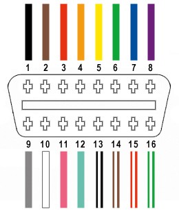 OBD2 Connector Pinout Diagram
Step-by-Step Guide: Building Your OBD2 Adapter Cable
Let’s proceed with the step-by-step instructions to assemble your OBD2 adapter cable.
Step 1: Preparing the OBD-II Cable (OBD2C)
- Separate and Isolate Wires: Begin by carefully removing the outer sheath and shielding from a section of the OBD2C. You only need to expose the four wires we will be using (pins 4, 6, 14, and 16).
- Identify Target Wires: Locate the orange, green, and two green w/white stripe wires within the OBD2C. These correspond to the pins listed earlier.
- Isolate Unused Wires: Bundle the remaining 12 wires (the ones you won’t be using) together and secure them with a zip tie to keep them out of the way. This prevents them from interfering with your work and keeps the workspace tidy.
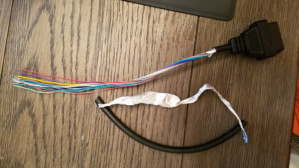 Stripped sheath and shielding of OBD2 cable
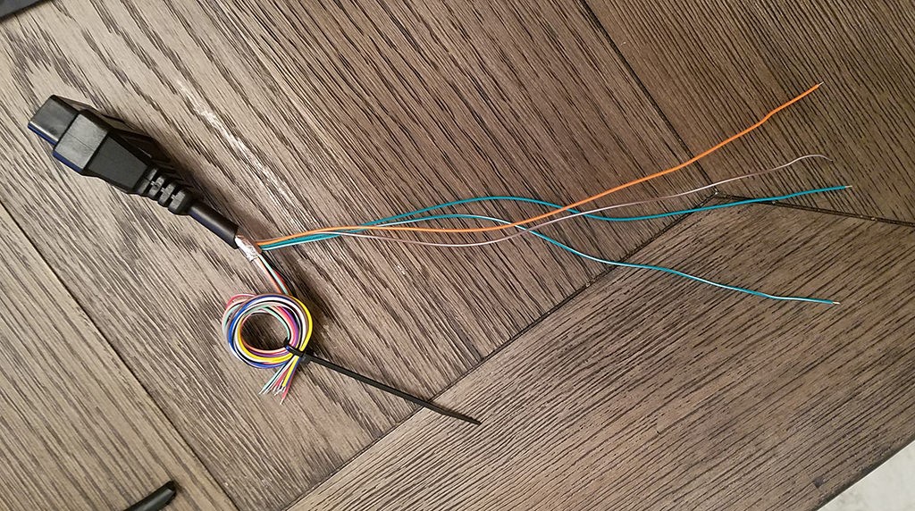 Separated wires for OBD2 adapter cable
Step 2: Preparing the Wires and Seals for the 4-Pin Connector (4PC)
- Address Wire Gauge Mismatch: The wires in the OBD2C are often 26AWG, which is thinner than the 22AWG-sized pins of the 4-pin connector (4PC) we are using. To compensate for this, we need to “thicken” the wire ends.
- Strip Wire Ends: The OBD2C wires come pre-stripped with a small amount of exposed wire (approximately 1/8″). Strip off more insulation to expose about 3/8″ of wire.
- Fold and Twist: Fold the exposed wire back over itself and twist the doubled wire strands tightly. This effectively doubles the wire thickness, making it a better fit for the 4PC pins.
- Slide on Rubber Seals: The 4PC kit should include rubber seals. Slide one rubber seal onto each of the four prepared wires. These seals provide environmental protection and strain relief once the pins are inserted into the connector housing.
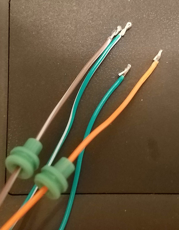 Preparing wires and seals for 4-pin connector
Step 3: Attaching Wires to 4-Pin Connector Pins
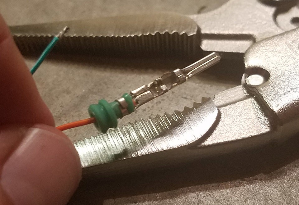
- Pin Structure: Examine the pins for the 4PC. You’ll notice two sets of prongs. The front prongs are designed to crimp onto the exposed wire, and the rear prongs crimp onto the rubber seal for strain relief.
- Insert Wire: Insert the prepared wire into the front of the pin, positioning it so that the exposed wire sits between the front prongs. The wire may seem small compared to the pin, as shown in the image.
- Secure Wire (Needle-Nose Pliers): Due to the small wire size, it can be helpful to use needle-nose pliers to hold the wire firmly in place against the pin during the next step, especially if you are soldering.
 Attaching wire to 4-pin connector pin
Step 4: Soldering or Crimping the Wires
Soldering (Recommended):
- Solder for Secure Connection: Soldering provides a robust and electrically sound connection, which is highly recommended for this project, particularly with the thin 26AWG wires.
- Apply Solder: Carefully apply solder to the area where the wire is in contact with the front prongs of the pin. Ensure the solder flows smoothly and creates a solid bond.
- Soldering Tips: If you are new to soldering, there are many helpful resources available online. This YouTube video provides useful soldering tips and tricks.
Crimping (Alternative):
- Use Crimping Tool (Recommended): If you have a Molex crimping tool, use it to crimp the front prongs of the pin securely around the wire. Follow the tool’s instructions for proper crimping technique.
- Crimping with Needle-Nose Pliers (Alternative): If you don’t have a crimping tool, needle-nose pliers can be used, but require more care. Use the pliers at an angle to gently fold one prong over the wire, then repeat for the other prong. This video demonstrates crimping with pliers.
- Ensure Secure Crimp: Regardless of the method, ensure the prongs are firmly crimped around the wire to create a good mechanical and electrical connection. You can use pliers to further crush the prongs down for added security if needed.
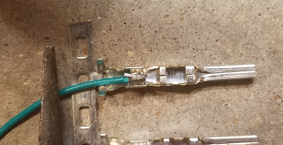
 Soldering wire to connector pin
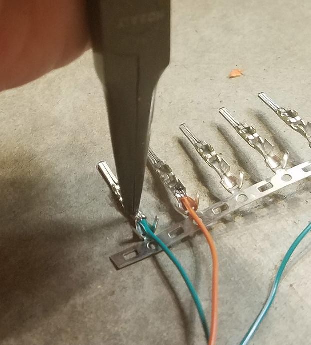 Crimping connector pin with pliers
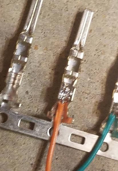
 Crimped connector pin detail
Step 5: Securing the Seals
- Slide Seal into Position: Slide the rubber seal up the wire until it sits between the rear prongs of the connector pin.
- Crimp Rear Prongs: Use the same crimping technique (either with a crimping tool or needle-nose pliers) to fold the rear prongs over the rubber seal. This secures the seal and provides strain relief for the wire, protecting the soldered/crimped connection.
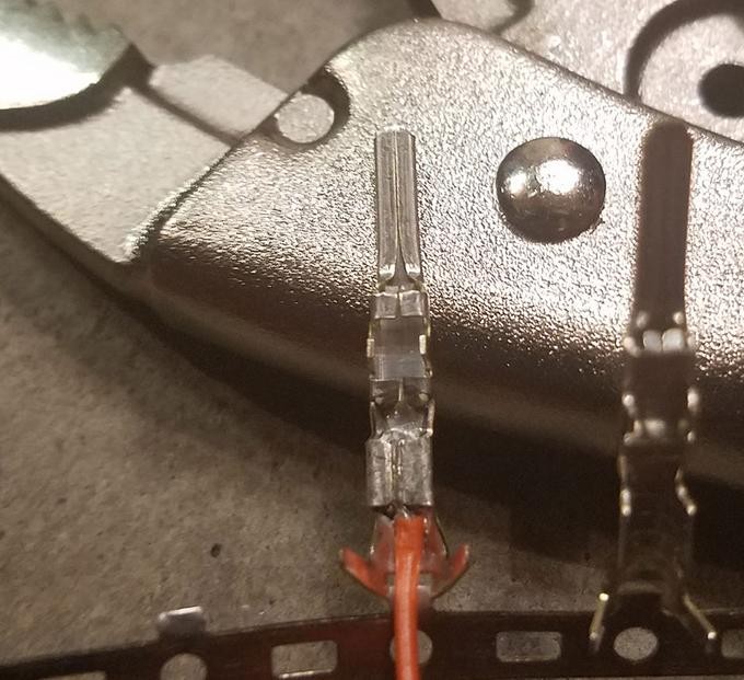
 Positioning rubber seal for crimping
 Crimping rear prongs over rubber seal
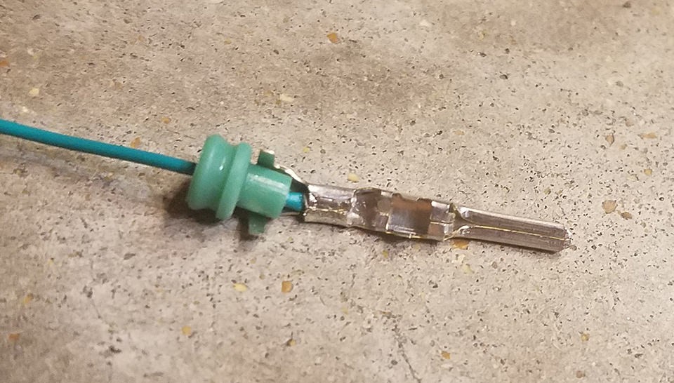
 Completed crimped pin with seal
Step 6: Twisting Wire Pairs
- Pair Wires: Pair the wires as follows:
- Pin 4 (orange) / Pin 16 (green w/white stripe)
- Pin 6 (green) / Pin 14 (brown w/white stripe)
- Twist Pairs: Twist each wire pair together. While the exact reason for twisting isn’t definitively stated in all guides, it’s often recommended in automotive wiring for potential noise reduction and signal integrity, especially for CAN bus signals.
Step 7: Inserting Pins into the 4-Pin Connector
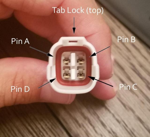
- Connector Orientation: Refer to the 4-pin connector housing and the pinout diagram below to ensure correct pin insertion.
- Pin Insertion Order: Insert the pins into the 4PC housing in the following orientation:
- Pin 14 (brown w/white stripe) > connector slot A
- Pin 6 (green) > connector slot B
- Pin 16 (green w/white stripe) > connector slot C
- Pin 4 (orange) > connector slot D
- Insert and Lock: Insert each pin into the rear of the connector housing until you hear an audible “click.” This click indicates that the pin is properly locked into place. You can use needle-nose pliers to gently pull on the wire from the rear to ensure the pin is securely locked.
 4-Pin connector pin insertion
Testing Your DIY OBD2 Adapter Cable
Congratulations! You have now completed your DIY OBD2 adapter cable.
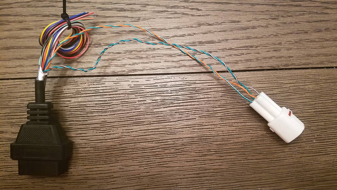 Completed OBD2 adapter cable
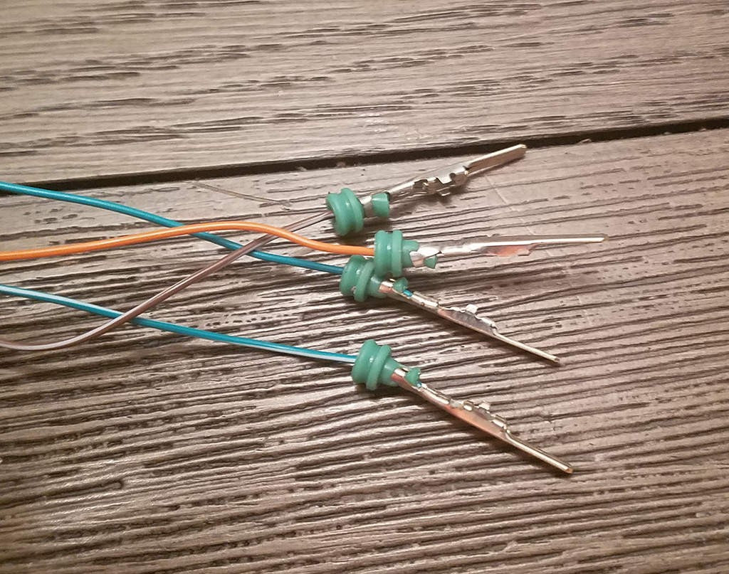
 OBD2 adapter cable connectors
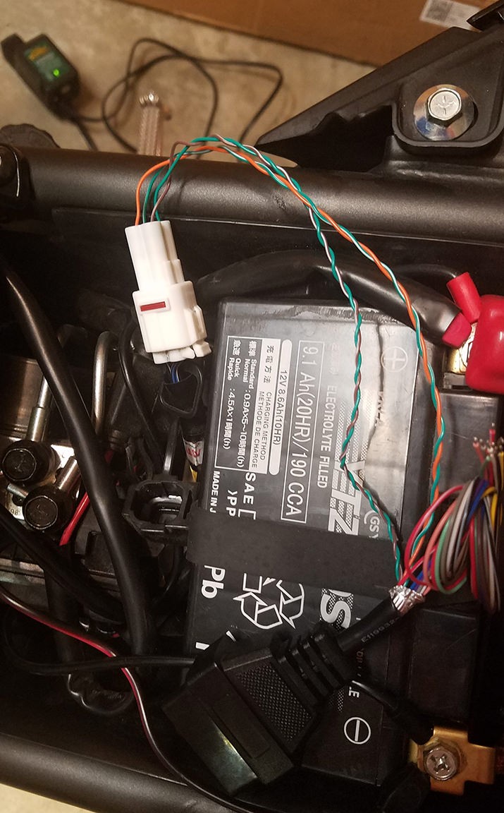
To test your cable, connect it to your vehicle’s OBD2 port and your diagnostic tool or system using the 4-pin connector. In the original test, the cable was successfully used to read and clear a self-induced error code.
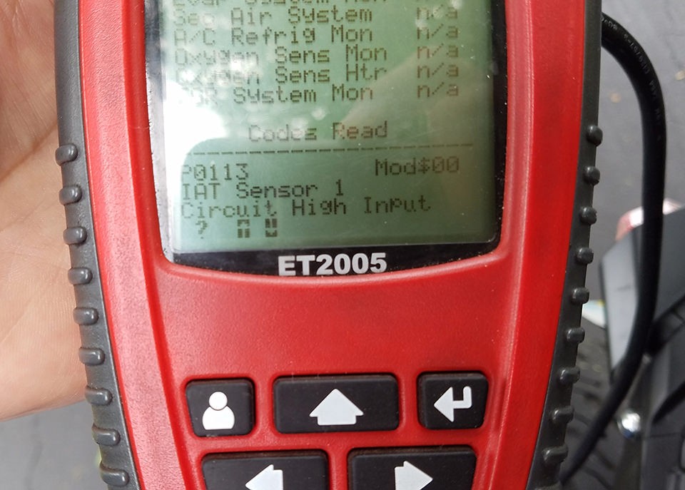 Testing OBD2 adapter cable
Conclusion
Building your own OBD2 adapter cable is a practical and educational DIY project. By following these steps, you can create a custom cable tailored to your needs, potentially saving money and gaining valuable experience in automotive wiring and diagnostics. Remember to always double-check your connections and exercise caution when working with vehicle electrical systems.
While this guide is based on personal experience and aims to be helpful, it’s important to reiterate that we are sharing this as a DIY enthusiast, not a professional. If you encounter issues or are unsure about any step, consult with qualified automotive professionals. Enjoy the process and the satisfaction of using your own custom-built OBD2 adapter cable!
